

System and method for acquiring bus passenger flow information
A technology of information collection and collection subsystem, which is applied in the fields of electronic and electrical technology and computers, can solve the problems of difficulty in collecting bus passenger flow information and low accuracy, and achieve the effects of high accuracy, less human intervention, and saving human resources
- Summary
- Abstract
- Description
- Claims
- Application Information
AI Technical Summary
Problems solved by technology
Method used
Image

Examples
Embodiment
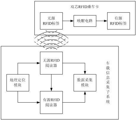
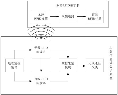
[0056] This embodiment utilizes the technical solution of the present invention to construct a bus passenger flow information collection system, using a dual-core RFID boarding card as a public transportation boarding card for citizens, and a vehicle-mounted information collection subsystem is installed on each bus of the public transport system .
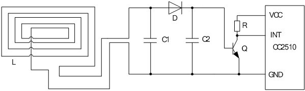
[0057] In the system, the dual-core RFID travel card includes a passive RFID tag, a wake-up circuit and an active RFID tag that are electrically connected in sequence. Passive RFID tags are obtained through commercially available mature products, and the working frequency of the RFID chip in the passive RFID tags is 13.56MHz, following the ISO14443 protocol. The active RFID tag is developed using the commercially available wireless transmission control chip CC2510 as the core. The CC2510 chip contains an 8-bit MCU (namely 8051), a 2.4GHz radio frequency transceiver (with a data transmission and reception rate of 250kbps), and a 32 ...
PUM
 Abstract
Description
Claims
Application Information