Embedded programmable multi-wave shape PDLC (polymer dispersed liquid crystal) driving power supply and control method

A drive power, multi-waveform technology, applied in the direction of instruments, static indicators, etc., to achieve the effect of easy control, flexible and convenient use, and small size

Inactive Publication Date: 2012-07-18
UNIV OF SHANGHAI FOR SCI & TECH
4 Cites 15 Cited by

AI-Extracted Technical Summary

Problems solved by technology

[0004] The present invention aims at the problem that the optoelectronic characteristics of the new optical material polymer-dispersed liquid crystal are in the research stage, and proposes an embedded programmable multi-waveform PDLC drive power supply a...

Abstract

The invention relates to an embedded programmable multi-wave shape PDLC (polymer dispersed liquid crystal) driving power supply and a control method, wherein a signal collecting module collects an output signal of a PDLC in real time and sends the output signal to an ARM (Advanced RISC Machines) control module, the ARM control module outputs a control signal to a signal generating module, the output signal of the signal generating module is modulated by a signal modulating module and is amplified by a power amplifying module, and the amplified signal is sent to a boosting module to be boosted so as to drive an LCD (liquid crystal display) touch screen. According to the invention, the polymer dispersed liquid crystal material is driven to generate an electric control phenomenon on the light, and a single path is adjustable and controllable, the output signal of the PDLC is collected and displayed on the touch screen. The system of the invention provides an experiment foundation for research on photoelectric properties of PDLC material, and the system integrates such functions as driving the power supply, controlling and adjusting the signal, displaying the wave shape and collecting data, and the like; besides, the system is small in volume, easy to control and convenient and flexible in application.

Application Domain

Technology Topic

Image

  • Embedded programmable multi-wave shape PDLC (polymer dispersed liquid crystal) driving power supply and control method
  • Embedded programmable multi-wave shape PDLC (polymer dispersed liquid crystal) driving power supply and control method
  • Embedded programmable multi-wave shape PDLC (polymer dispersed liquid crystal) driving power supply and control method

Examples

  • Experimental program(1)

Example Embodiment

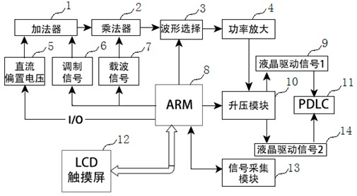
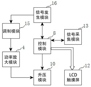
[0012] Such as figure 1 , 2 The schematic frame and module connection diagram of the embedded programmable multi-waveform PDLC drive power supply structure is shown. The drive power supply includes 7 modules: signal generation module 16, signal modulation module 15, ARM control module 8, power amplifier module 4, boost module 10 , Signal acquisition module 13, LCD touch screen 12, signal acquisition module 13 real-time acquisition of the output signal of PDLC polymer dispersed liquid crystal 11, the output signal is sent to ARM control module 8, ARM control module 8 outputs control signals to signal generation module 16, signal generation module 16 The output signal is modulated by the signal modulation module 15 and then amplified by the power amplifying module 4, and the amplified signal is boosted in the boost module 10 to drive the LCD touch screen 12.
[0013] The signal generation module 16 is completed by the hardware design of the signal generator, and consists of two-channel frequency synthesis device DDS waveform generator. A routing signal modulation module 15 superimposes the modulation signal 6 and the DC bias voltage signal 5 in the adder 1, and superimposes The signal is multiplied by another source carrier signal 7 in the signal generation module 16 in the multiplier 2 to obtain a standard amplitude modulation signal. The DC partial voltage is controlled by the digital potentiometer of frequency synthesis, so that the modulation signal 6, the source carrier signal 7 and the DC bias voltage signal 5 can generate different waveforms, which is convenient to drive the liquid crystal for comparison experiments. The ARM control module 8 controls the waveform selection 3 After that, the output goes through the power amplification 4 to the boost module 10.
[0014] ARM control module 8, single-channel distribution of two GPIO ports to simulate SPI bus, four channels of signals are distinguished by chip selection signals, the signal generation module 16 is controlled by ARM control module 8 to send and receive signals, sine wave, square wave, triangle wave waveform selection; Adjust the phase and frequency; control the signal modulation module 15 digital potentiometer to adjust the signal amplitude; control the boost module 10 to increase the driving voltage; control the signal acquisition module 13 to collect and store the PDLC output signal; control the LCD touch screen 12 to realize and adjust.
[0015] The power amplifying module 4 and the boosting module 10 are still based on the hardware design of a power amplifier and a transformer, and the latter realizes power amplification of weakly modulated signals. Since the electrical signals 9 and 14 required to drive the liquid crystal material must reach the threshold voltage required to drive the liquid crystal, the weak modulation signal 6 must be boosted to drive the liquid crystal material. Before boosting, the power amplification of the electrical signal is necessary. Finally, the signal acquisition module 13 displays the signal on the LCD touch screen 12 at the output end of the PDLC polymer dispersed liquid crystal 11 and collects and stores the signal in real time.
[0016] The upper software design realizes the GUI main control system image 3 , Abstract four levels: software application layer, such as waveform generator receiving and sending, waveform selection, digital potentiometer amplitude adjustment, etc.; event-driven layer: process management, window management, display system, information feedback, etc.; highly integrated C++QT Library, such as application program interface library; device driver layer: including touch screen driver, library interface driver, etc. The final realization of GUI control waveform generator, digital frequency synthesis potentiometer channel selection, multiplexer channel switch and channel number selection, power amplifier input and output waveform display and adjustment, terminal signal data acquisition and storage, AD converter switch.

PUM

no PUM

Description & Claims & Application Information

We can also present the details of the Description, Claims and Application information to help users get a comprehensive understanding of the technical details of the patent, such as background art, summary of invention, brief description of drawings, description of embodiments, and other original content. On the other hand, users can also determine the specific scope of protection of the technology through the list of claims; as well as understand the changes in the life cycle of the technology with the presentation of the patent timeline. Login to view more.

Similar technology patents

Strapping inertial navigation gyroscope clinometer based on MEMS device

InactiveCN101493008ARealize measurement while drillingReduce volumeSurveyTurn-sensitive devicesSpeed measurementContinuous measurement
Owner:BEIJING LIUHE GREATNESS TECH

Classification and recommendation of technical efficacy words

  • Easy to control
  • Reduce volume

Implant release mechanism

ActiveUS20080140178A1Reduce volumeReduce outer diameterStentsOcculdersDilatorStent
Owner:COOK MEDICAL TECH LLC

Flash storage chip and flash array storage system

ActiveUS20080052451A1Reduce volumeImprove data transmission rateMemory adressing/allocation/relocationData transmissionPCI Express
Owner:PHISON ELECTRONICS

Devices and methods for placement of partitions within a hollow body organ

InactiveUS20070167960A1Reduce volumeSuture equipmentsStapling toolsTissue acquisitionBody organs
Owner:ETHICON ENDO SURGERY INC
Why Eureka
Try Eureka