

Switched Reluctance Motor
Patent Information
- Authority / Receiving Office
- CN · China
- Patent Type
- Applications(China)
- Current Assignee / Owner
- SAMSUNG ELECTRO MECHANICS CO LTD
- Publication Date
- 2012-07-18
- Estimated Expiration
- Not applicable · inactive patent
Smart Images
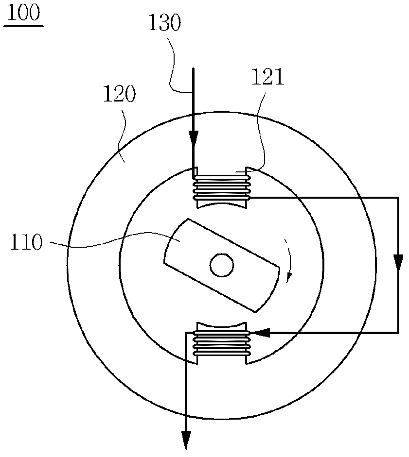
Figure 1 
Figure 2 
Figure 3
Abstract
Description
[0001] Cross References to Related Applications
[0002] This application claims priority to Korean Patent Application No. 10-2011-0002436, filed Jan. 10, 2011, entitled "Switched Reluctance Motor", the entire contents of which are hereby incorporated by reference in this application. technical field
[0003] The invention relates to a switched reluctance motor. Background technique
[0004] A general switched reluctance motor has a magnetic structure in which both the stator and the rotor are salient poles. In addition, the stator has coils wound intensively around the stator, and the rotor is formed of only an iron core without employing any exciting means such as windings, permanent magnets, etc. to have excellent price competitiveness. Further, the variable-speed switched reluctance motor can stably generate continuous torque by means of a converter using power semiconductor elements and position sensors, and can be easily controlled according to performance required f...