Signaling and reduced torque ripple in brushless repulsion motors

a brushless repulsion motor and torque ripple technology, applied in the direction of motor/generator/converter stopper, dynamo-electric converter control, etc., can solve the problems of torque or rotation, brush and commutator wear out, and the type of repulsion motor has not been widely adopted, so as to facilitate the low cost manufacturing of high-performance blr motors and facilitate precise control of specific rotor coils. , the effect of reducing torque rippl

Inactive Publication Date: 2007-01-23
DYNAMOTORS
View PDF14 Cites 37 Cited by
  • Summary
  • Abstract
  • Description
  • Claims
  • Application Information

AI Technical Summary

Benefits of technology

[0009]The present invention relates to brushless repulsion motors with rotor signal detectors spaced farther apart than in conventional BLR motors, and with stator mounted signaling devices angularly spaced around all or a substantial portion of the stator circumference. This feature may help to alleviate or avoid cross talk between illuminated LEDs or other stator-mounted signaling sources and signal detectors associated with non-selected rotor coils, thereby improving the ability to selectively control individual rotor coils in brushless repulsion motors without the additional cost associated with higher performance optical signaling and detector components. The invention also relates to asymmetric stator pole structures for BLR motors that may facilitate reduced torque ripple and the adverse effects associated therewith in brushless repulsion motors, where the distributed signaling source and asymmetric stator pole concepts of the invention may be employed separately or in combination in a given brushless repulsion motor design.
[0011]This aspect of the invention provides flexibility in detector location and may also include distribution of the stator-mounted signal sources (e.g., LEDs) around all or most of the stator circumference to facilitate precise control of specific rotor coils without cross talk and the resulting inadvertent shorting of non-selected rotor coils, even where the motor dimensions shrink and the number of stator poles and rotor coil segments increase. This, in turn, advantageously facilitates low cost manufacturing of high performance BLR motors using signaling and detector components that may have manufacturing tolerance variations. The detectors, moreover, need not be angularly aligned with the corresponding rotor coil as was the case in conventional BLR motors. Furthermore, the detector and signaling device spacing advantages may be employed in motors with symmetrical stator configurations wherein the individual torque sectors of the stator field have an angular length of about 360° / 2Ns, as well as in BLR motors having asymmetrical stator fields.
[0012]In accordance with another aspect of the invention, the stator of the BLR motor is asymmetrical, wherein the stator includes a plurality of stator poles and at least one field winding producing a stator field, with at least two of the stator poles being different. The asymmetrical stator configuration may be advantageously employed to significantly reduce torque ripple and the adverse effects associated therewith, wherein rotor coil segments of a shorted rotor coil encounter pole tips at different coil angles to effectively spread out the peak torque through a wider angle, which may include more than one peak. The peak torque spreading effect with respect to the torque contribution of individual rotor coils, in turn, reduces the net ripple for the composite torque of the motor. The stator pole asymmetry may be created regardless of the number of poles in a particular stator, by varying the structure of the pole surfaces, such as where first and second stator poles are formed that extend along different angular lengths. Where the stator includes multiple pole pairs, the asymmetry may be implemented by providing a first pole pair having first and second poles that are substantially identical to one another and angularly offset from one another by about 180°, along with a second pole pair comprising third and fourth poles substantially identical to one another and angularly offset by about 180° from one another, where at least two of the first, second, third, and fourth stator poles are different. In another related aspect, the stator is formed using a plurality of stator laminations or sections arranged in a stack to form a plurality of stator poles, where the stator sections individually provide two or more pole portions with at least two of the pole portions being different to provide an overall asymmetrical stator for a BLR motor. In one implementation, at least two of the stator sections are angularly staggered with respect to one another in the stack with different pole portions of the two stator sections aligned with one another.

Problems solved by technology

This type of repulsion motor has not been widely adopted because the brushes and commutator wear out quickly due to arcing and heat generated by the brushes contacting the commutator.
However, when the switch is open, current cannot flow and no torque or rotation is produced by that coil.
In this regard, the conventional two pole BLR motors may also suffer from significant torque ripple, where the peak torque occurs as a shorted rotor coil passes near a stator pole tip.
Where multiple rotor coils are used, the torque peaks of individual coils are separated in time and combine to produce a ripple effect in the total produced torque, which can lead to vibration, noise, premature bearing wear, and other problems in BLR motors.
This may lead to crosstalk situations in which non-selected rotor coils are shorted when the associated optical detector is proximate a lighted LED.
Light dispersion effects in LEDs and other optical signaling devices become more pronounced as the motor dimensions are reduced and as the number of stator poles and rotor coil segments increase, thereby making the manufacture of BLR motors with consistent operational performance more difficult.
One manufacturing difficulty is variation in LEDs, in which light provided by a given LED establishes a corresponding light distribution or pattern (cone), with distributions varying according to LED type, manufacturing production lot, vendor, orientation, current supply, age, temperature, and LED-to-detector distance.
These production variations in LED signaling source patterns make it difficult to provide precise illumination spots such that the rotating detectors and corresponding switching circuitry of the rotor are activated at exactly the desired time and place without undesired activation of detectors associated with non-selected rotor coils.
Such difficulties may be addressed by using more coherent light sources or fiber optic devices, but these solutions are costly.

Method used


Image

  • Signaling and reduced torque ripple in brushless repulsion motors
  • Signaling and reduced torque ripple in brushless repulsion motors
  • Signaling and reduced torque ripple in brushless repulsion motors

Examples


Embodiment Construction

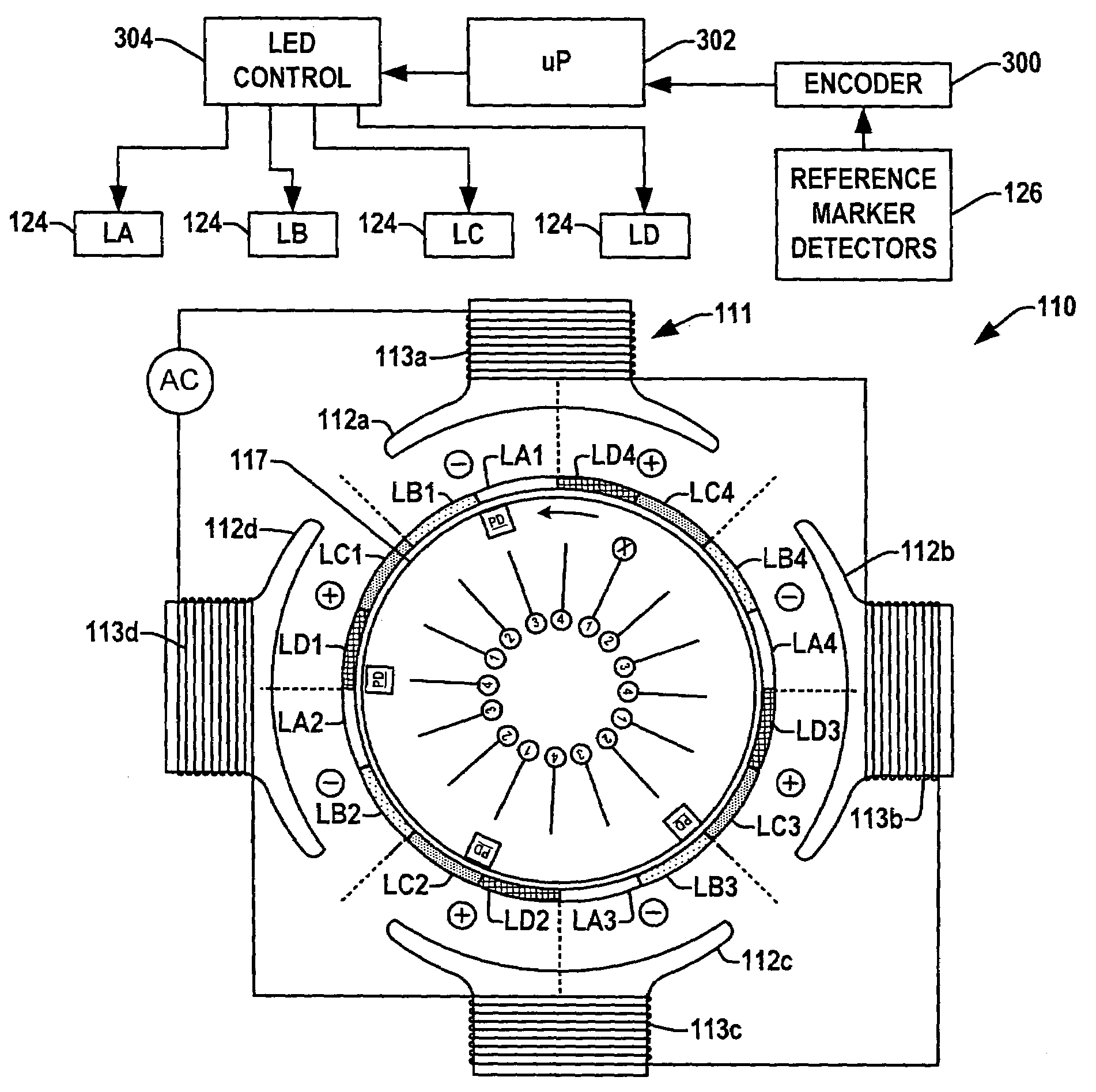
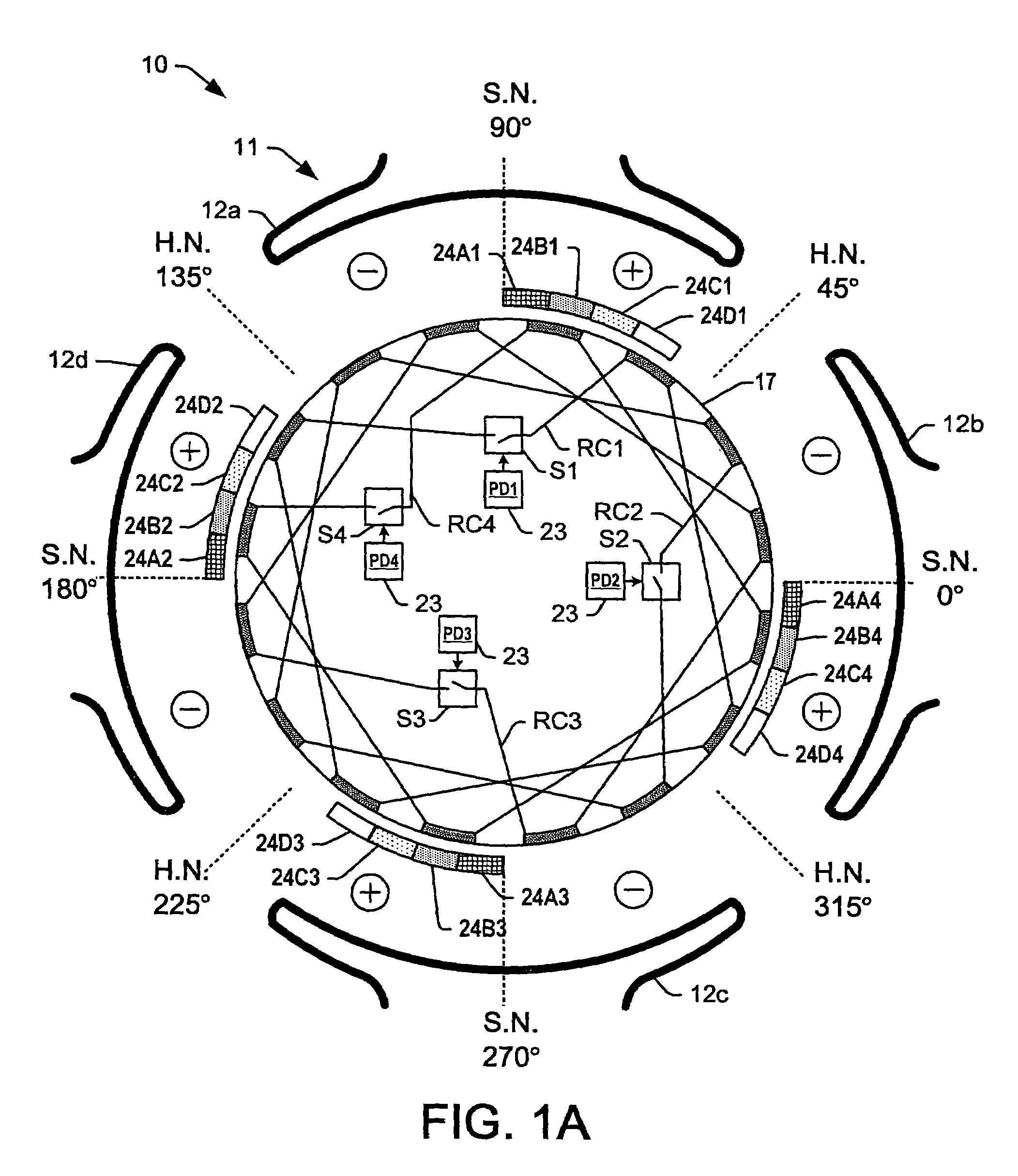
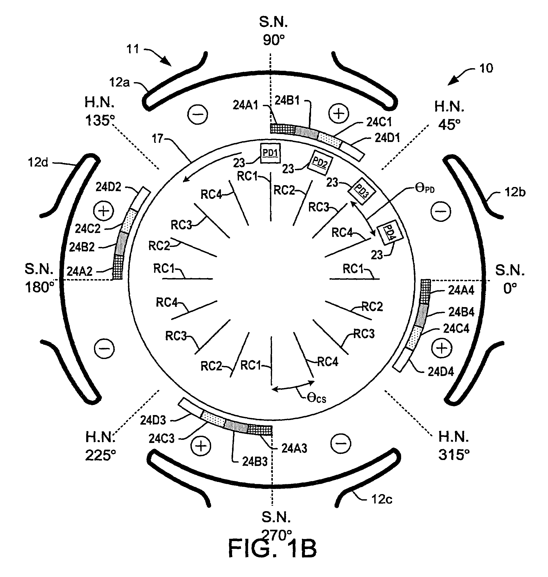
[0031]One or more exemplary implementations of brushless repulsion motors are hereinafter illustrated and described in accordance with the present invention, wherein like reference numerals are used to refer to like elements throughout and wherein the illustrated structures are not necessarily drawn to scale. The invention relates to improved brushless repulsion motors in which rotor-mounted detectors and stator-mounted signaling sources are more widely spaced that in previous BLR motors to facilitate the use of increased numbers of stator poles and / or rotor coil segments while allowing selective activation of single rotor coils, as well as asymmetrical stator pole structures for alleviating torque ripple. While illustrated and described hereinafter in specific embodiments using optical signaling and detector devices, other signaling components and detectors can be used, including but not limited to optical devices, magnetic devices, RF devices, etc., wherein all such variant implem...


PUM


Abstract

Brushless repulsion motors are presented, in which rotor coils switching signal detectors are selectively located in spaced angular relationship on the rotor and signaling sources are distributed around all or most of the stator circumference to allow looser tolerances for motor manufacturing and improved controllability of rotor coil actuation during operation. Asymmetric stator poles are also provided for brushless repulsion motors to mitigate torque ripple and vibration, in which the shape of the stator pole tips is tailored by varying the angular length of the pole section.

Description

FIELD OF THE INVENTION[0001]The present invention relates generally to electric motors and more particularly to improved brushless repulsion motors with improved rotor coil switch signaling and reduced torque ripple.INCORPORATION BY REFERENCE[0002]Brushless repulsion motors and related technology are shown in the following U.S. patents: Haner U.S. Pat. No. 5,424,625; Haner U.S. Pat. No. 6,049,187; Haner U.S. Pat. No. 6,108,488; and Jones U.S. Pat. No. 6,321,032, the entireties of which are hereby incorporated by reference as if fully set forth herein.BACKGROUND OF THE INVENTION[0003]Repulsion motors have torque speed performance curves and other performance characteristics similar to those of series DC motors and universal series motors, and also offer high starting torque with comparatively low starting current, and the ability to sustain the high starting torque for long periods of time. This type of motor is also adaptable to a wide range of controllable speeds, wherein the no lo...

Claims


Application Information

Patent Timeline
Patent Type & Authority Patents(United States)
IPC IPC(8): H02P6/08H02K1/18
CPCH02K17/12H02K29/10H02K23/64
Inventor JONES, WILLIAMKILMO, ROBERT G.TOMAN, DOUGLAS A.NEWMAN, WYATT S.
Owner DYNAMOTORS
Why Eureka
Try Eureka