High reliability motor system

a motor system and high reliability technology, applied in the direction of motor/generator/converter stopper, dynamo-electric converter control, magnetic circuit shape/form/construction, etc., can solve the problem of completely disabling the operation of a conventional motor system, and achieve the effect of reducing the risk of phase to phase shortag

Inactive Publication Date: 2005-04-26
STRIDSBERG LICENSING
View PDF10 Cites 34 Cited by
  • Summary
  • Abstract
  • Description
  • Claims
  • Application Information

AI Technical Summary

Benefits of technology

[0006]It is an object of the invention to provide a brushless electric motor system having dramatically reduced risk of phase to phase shortages.

Problems solved by technology

All these failure modes will completely disable the operation of a conventional motor system.

Method used


Image

  • High reliability motor system
  • High reliability motor system
  • High reliability motor system

Examples


Embodiment Construction

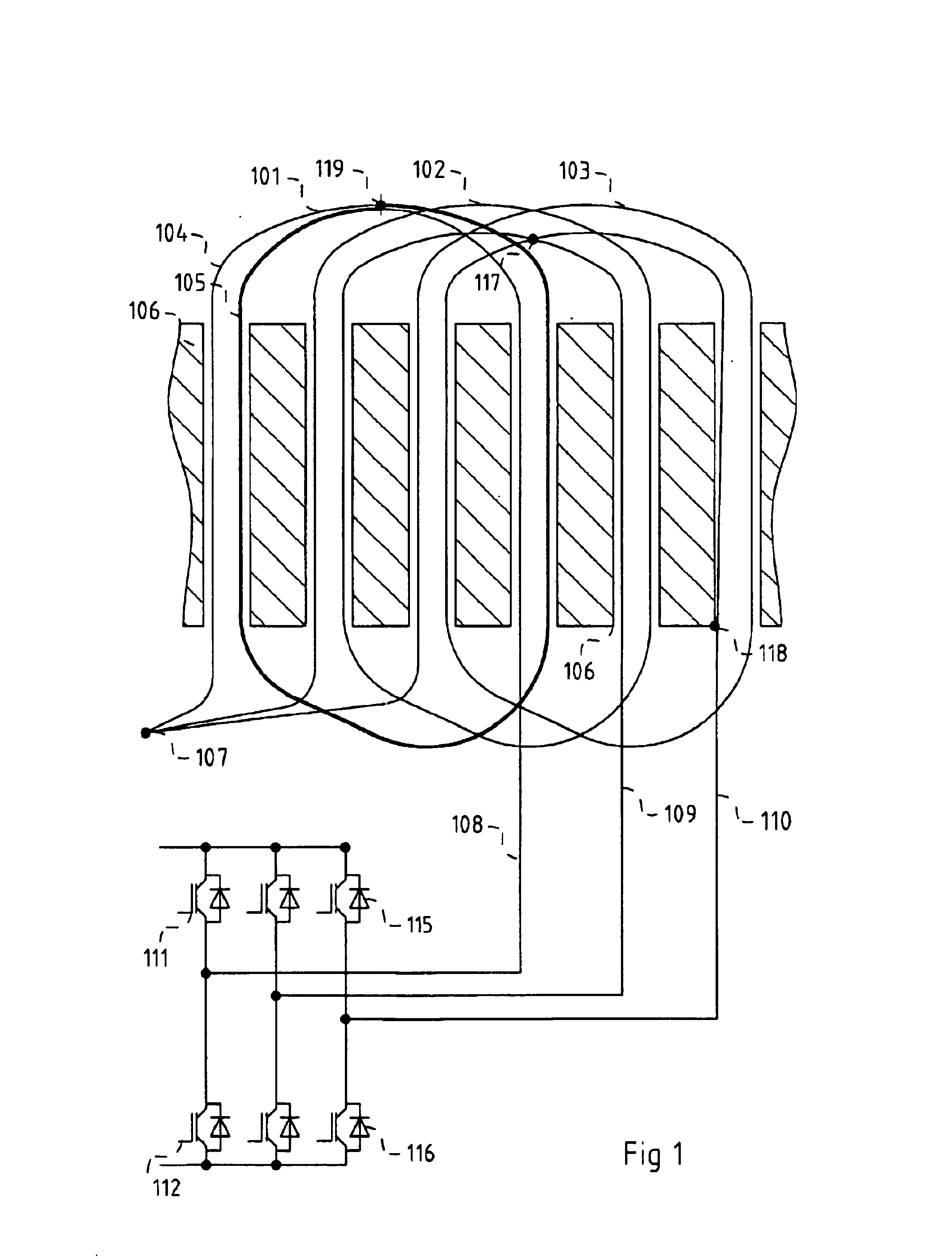
[0033]In FIG. 1 the principle layout of the electric windings and their connection in a conventional brushless electric motor is illustrated. The illustrated motor has three stator windings 101, 102 and 103 connected to three phases and arranged in slots between poles of a laminated iron stator pack 106, the poles projecting towards the rotation axis, not shown, of the motor. Each phase winding is illustrated as a coil having only two turns such as 104 and 105. All the phase coils have one end interconnected, at a common node 107. Any part of any winding is connected to all other parts of all windings through metallic conductors. The other ends 108, 109 and 110 of the phase coils are connected to a switching circuit, in particular to the interconnection nodes of pairs of power switches 111 and 112, 113 and 114, 115 and 116, the switches of each pair connected in series between two rails connected to a power supply, not shown.

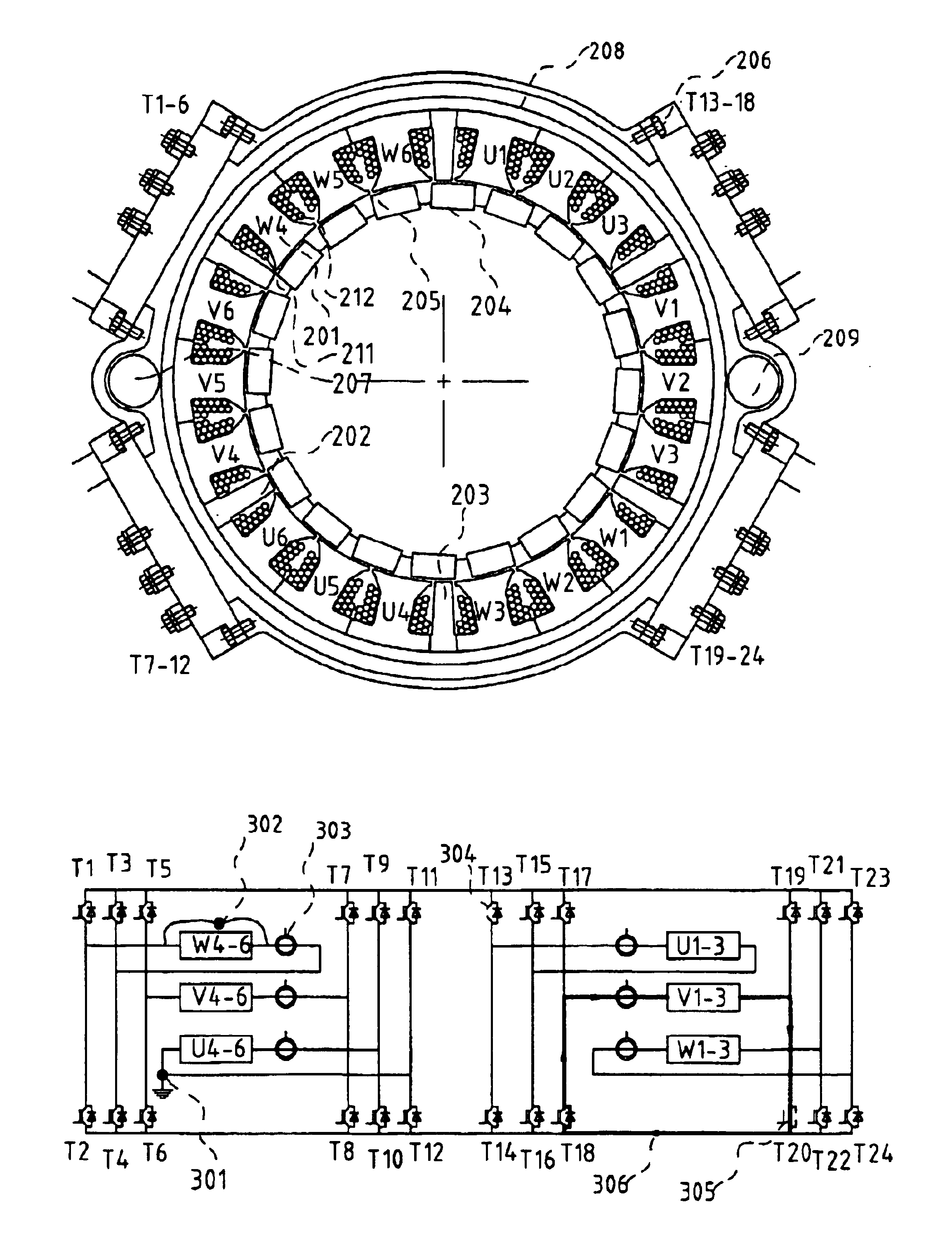
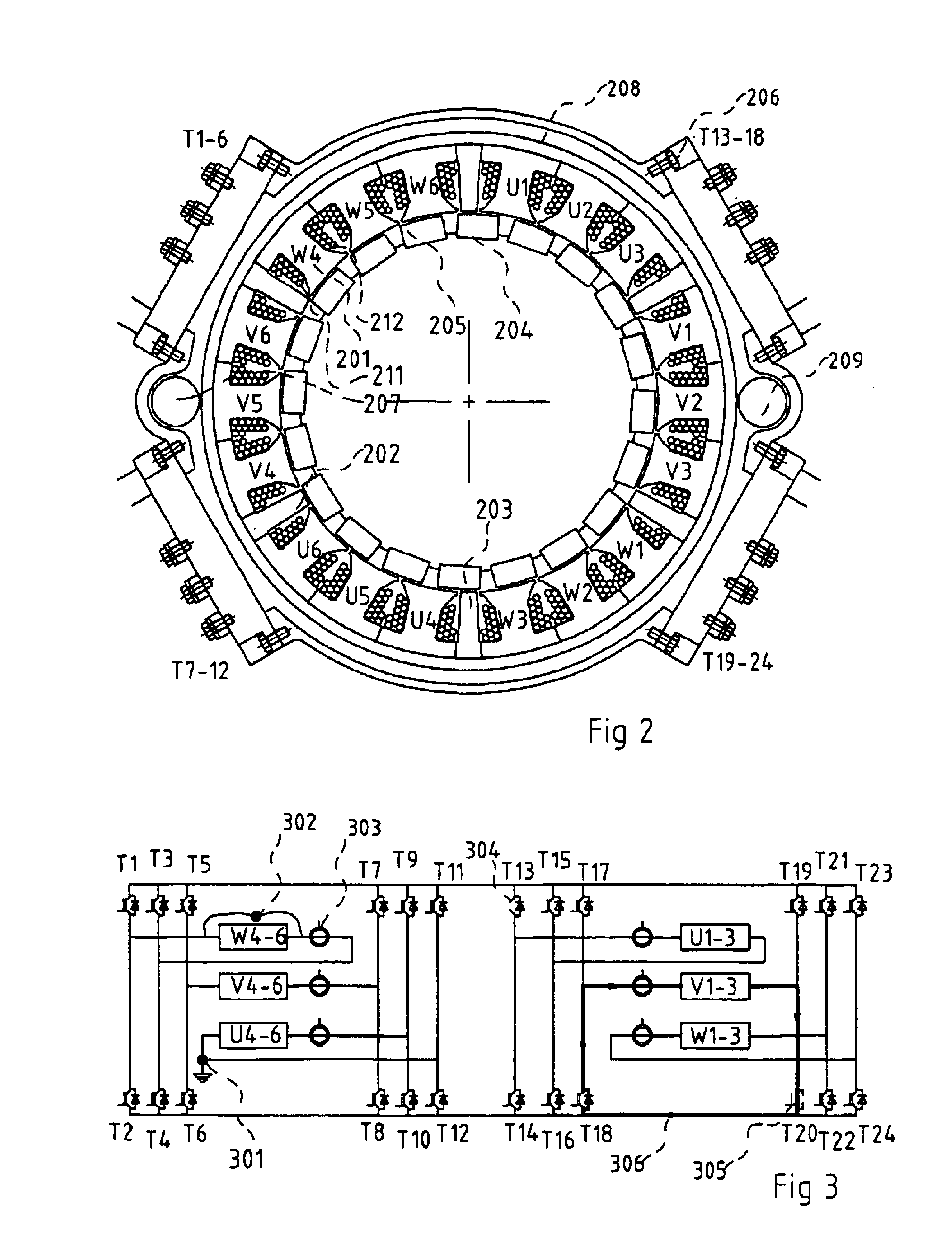
[0034]In FIG. 2 a cross-section of a brushless electric mo...


PUM


Abstract

A brushless electric motor system comprises a rotor and a stator comprising poles. Electrical phase windings have coils (U1-6, V1-6, W1-6) wound around the poles. Power switches (T1-24) controlled by a control device supply electric current the windings from positive and negative rails connected to power supply. For each phase at least one group of four power switches arranged in a H-bridge configuration is provided. The coils of each phase winding are preferably divided into winding group (U1-3, Ua-6, V1-3, V4-6, W1-3, W4-6) and the electric conductor of each winding group is then electrically conductor of the other winding groups. Then four power switches arranged in an H-configuration is provided for each winding group. The use of power switches in H-bridge configurations allows the faulty windings or winding groups to be disabled and that the rest of the windings or coils can be used for driving the rotor, this giving the motor system a high reliability. The current supplied to other windings or winding groups can then be increased to compensate for the faulty group. The coil groups can be separated from other coil groups by unwound stator poles. Current sensors (303) can sense the current in each winding group and be used to detect whether the currents are too high. The sensed currents can be used to identify fault conditions in the system so that then suitable switches can be disabled, disconnecting a faulty winding group.

Description

[0001]This application is the national phase under 35 U.S.C. §371 of PCT International Application No. PCT / SE02 / 00233 which has an International filing date of Feb. 8, 2002, which designated the United States of America.TECHNICAL FIELD[0002]The present invention generally relates to brushless electric motor systems having high reliability and to methods of designing such motor systems.BACKGROUND OF THE INVENTION[0003]Brushless electric motor systems have several failure modes, some of which are illustrated in FIG. 1. The illustrated motor has three stator phases 101, 102 and 103. Each phase is illustrated as a coil having only two turns such as 104 and 105. The phase coils pass through slots in a laminated iron stator pack 106. One end of each of the phase coils is connected to a common node at 107. The other ends 108, 109 and 110 of the phase coils are connected to a three phase bridge having six power switches 111, . . . , 116.[0004]The fast switching of the transistors give high ...

Claims


Application Information

Patent Timeline
Patent Type & Authority Patents(United States)
IPC IPC(8): H02K3/28H02P29/02H02P6/08H02K11/04H02K11/00
CPCH02K3/28H02P29/02H02K11/046H02P6/085H02K11/0073H02K11/00H02K11/33H02K11/05
Inventor STRIDSBERG, LENNART
Owner STRIDSBERG LICENSING
Why Eureka
Try Eureka