Circuit configuration for a starting device

a starting device and circuit configuration technology, applied in the direction of engine starters, control systems, electric generator control, etc., can solve the problems of temporary voltage drop and high starting current in the electrical system of battery-operated vehicles, and achieve the effect of easy adaptation

Inactive Publication Date: 2014-11-25
ROBERT BOSCH GMBH
View PDF13 Cites 5 Cited by
  • Summary
  • Abstract
  • Description
  • Claims
  • Application Information

AI Technical Summary

Benefits of technology

[0009]An object of the present invention is to refine a circuit configuration, a method for operating the circuit configuration and a starting device of the type described above in such a way that an electric machine is operated as easily and in a manner that is as resource-saving as possible.
[0010]One idea of the present invention is that the circuit configuration for an electric machine includes a bridging device for bridging a current limiting device, and that a starting current of the electric machine is limited during the startup with the aid of the current limiting device, and the current limiting device is subsequently bridged by the bridging device. The circuit configuration may thus be used to limit the starting current of the electric machine and to operate the electric machine at full power, in particular after the startup, in that the current limiting device is bridged so that, in particular, a maximum current feed is achieved. The electric machine may thus be easily operated with the aid of a current limiting device in that the current limiting device may be deactivated by simply bridging the device. Furthermore, a resource-saving operation of the electric machine is possible, since a more powerfully dimensioned electrical supply or also protective measures for other electrical consumers are avoided by reducing the voltage drop during the startup of the electric machine.
[0011]It is preferred that the electric machine be situated in a motor vehicle and, in particular, operated via a battery-fed vehicle electrical system. The current-limiting device may be used to limit the electric load of the vehicle electrical system and still operate the electric machine at a maximum power with the aid of the bridging device, so that the battery of the vehicle electrical system may be dimensioned for less power, i.e., using fewer resources.

Problems solved by technology

On the other hand, it is the low impedance and, in particular, the low ohmic resistance, as well as the low inductivity, which result in high starting currents and a temporary voltage drop in a battery-operated vehicle electrical system.

Method used


Image

  • Circuit configuration for a starting device
  • Circuit configuration for a starting device
  • Circuit configuration for a starting device

Examples


Embodiment Construction

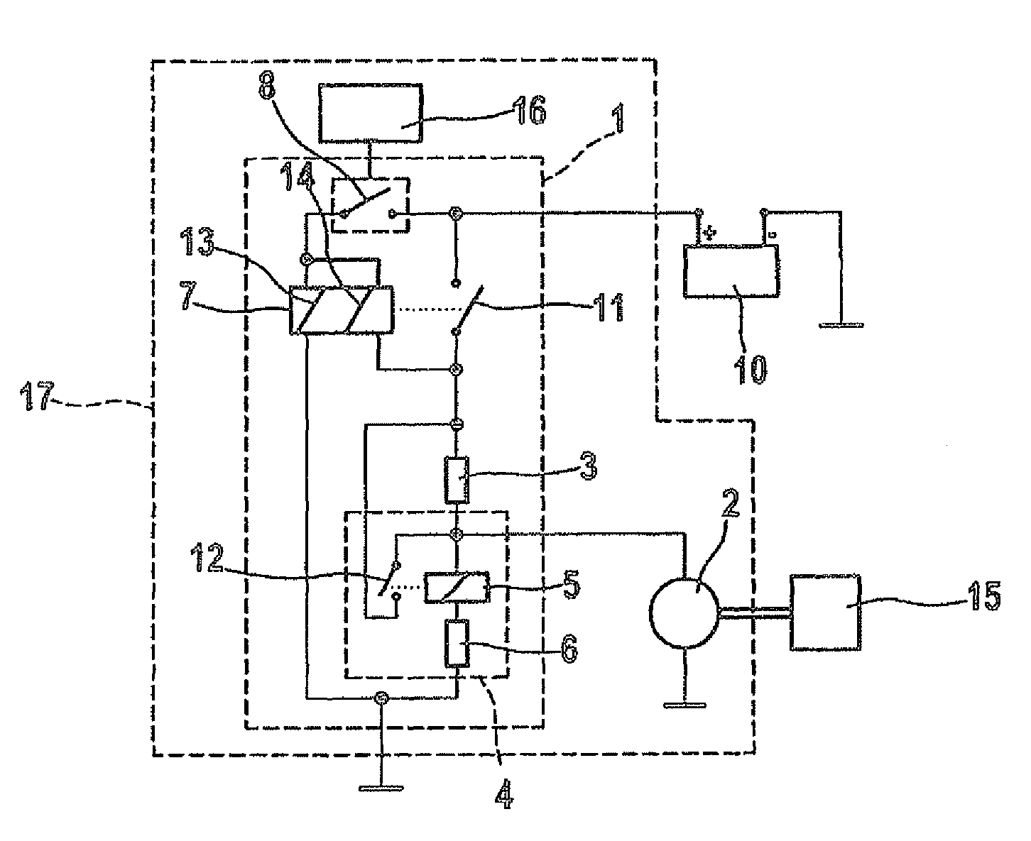
[0041]FIG. 1 shows a starting device 17 for starting an internal combustion engine 15 in a motor vehicle, which is not illustrated, including a circuit configuration 1 and a starter motor 2. Circuit configuration 1 is designed for an electric machine 2, namely for starter motor 2, for starting internal combustion engine 15 in the motor vehicle, including a current limiting device 3, namely a starting resistor, for limiting a starting current of starter motor 2. Circuit configuration 1 furthermore includes a bridging device 4 for bridging current limiting device 3, which includes a switching relay 5 and a variable resistor 6. In addition, circuit configuration 1 includes a conventional starter relay 7, which is designed, in particular, to activate and deactivate a current feed of starter motor 2 with the aid of a starter relay contact 11. Circuit configuration 1 is controlled by a start-stop controller 16, which ultimately controls the current feed of starter motor 2 via a switching ...


PUM


Abstract

A circuit configuration for an electric machine, e.g., a starter motor for starting an internal combustion engine in a motor vehicle, includes a current limiting device for limiting a starting current of the electric machine. The circuit configuration includes a bridging device for bridging the current limiting device.

Description

BACKGROUND OF THE INVENTION[0001]1. Field of the Invention[0002]The present invention relates to a circuit configuration for an electric machine, e.g., a starter motor for starting an internal combustion engine in a motor vehicle, including a current limiting device for limiting a starting current of the electric machine, and the present invention also relates to a method for operating a circuit configuration of this type.[0003]2. Description of Related Art[0004]Starting devices which are configured to have a starter motor according to the principle of a direct-current machine which uses mechanical commutation, in particular as a rotating-armature machine, are used for starting internal combustion engines in motor vehicles.[0005]To achieve a necessary high torque and a high power of the starter at a comparatively low vehicle electrical system voltage of approximately 12 V to 14 V, or 24 V to 28 V, the direct-current machine is equipped with a small number of windings and a large lin...

Claims


Application Information

Patent Timeline
Patent Type & Authority Patents(United States)
IPC IPC(8): F02N11/00
CPCF02N11/0814F02N11/0859F02N11/0862F02N11/087F02N2300/106
Inventor VENKATASUBRAMANIAM, BALASUBRAMANIAMHARTMANN, SVENTUMBACK, STEFANSENGEBUSCH, FALCOPIRSCH, ROMAN
Owner ROBERT BOSCH GMBH
Why Eureka
Try Eureka