Component for limiting currents in electric circuits

A current and current limiter technology, applied in emergency protection circuit devices, electrical components, circuit devices, etc. for limiting overcurrent/overvoltage, can solve problems such as electromagnetic interference, reduce wall thickness, reduce electromagnetic interference, etc. Interference, weight reduction effect

Active Publication Date: 2012-08-22
ROBERT BOSCH GMBH
View PDF4 Cites 5 Cited by
  • Summary
  • Abstract
  • Description
  • Claims
  • Application Information

AI Technical Summary

Problems solved by technology

However, an undesired side effect of said solution is electromagnetic

Method used


Image

  • Component for limiting currents in electric circuits
  • Component for limiting currents in electric circuits
  • Component for limiting currents in electric circuits

Examples


Embodiment Construction

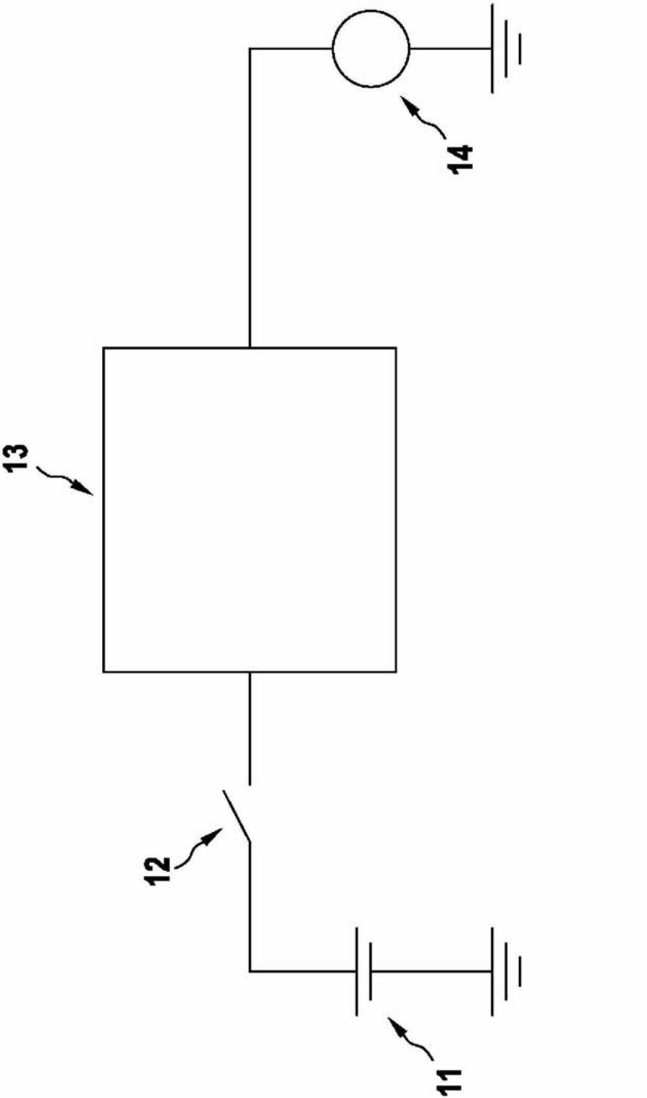
[0027] figure 1 A starter system of a motor vehicle with a flow restrictor 13 according to the invention is shown. A starter battery 11 is used as a power source, which is connected to a current limiter 13 via a starter relay 12 . On the output side, the current limiter 13 is in turn connected to an electric starter 14 which starts the internal combustion engine (not shown). If the internal combustion engine is to be started, starter relay 12 is closed by a suitable control signal, so that the battery voltage of starter battery 11 is supplied to current limiter 13 and via the current limiter to electric starter 14 in order to supply it. Because the electric starter 14 induces very large current peaks at the instant of starting, the current limiter 13 limits the current flowing from the starter battery 11 to the starter 14 .

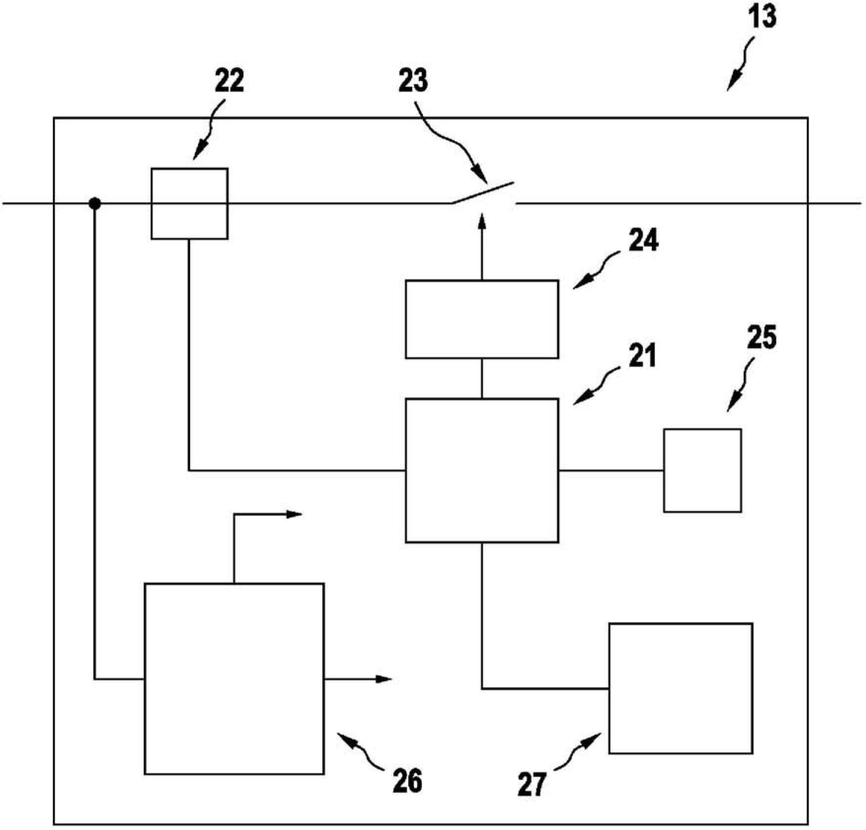
[0028] figure 2 A block diagram of a current limiter 13 according to the invention is shown. The current limiter 13 has a connecting line which lead...


PUM


Abstract

The invention relates to a current limiter comprising an input for a supply voltage source and an output for an output voltage. The current limiter has at least one control circuit, a current sensor which is designed to measure a current from the input of the current limiter to the output of the current limiter and to output a measured value to a measured value input of the control circuit, and at least one circuit breaker which is connected between the input and the output of the current limiter and which has a control input connected to a control output of the control circuit. The control circuit is designed to limit the current from the input of the current limiter to the output of the current limiter if the measured value exceeds a current threshold value. The control circuit is further designed to operate the at least one circuit breaker in the linear region.

Description

Background technique [0001] If the current rises above a magnitude determined according to the application (overcurrent), it can endanger the electrical installation due to heating. Overcurrent may also be an indication of a fault in the electrical system. [0002] Typically, current is limited by fuses. The fuse interrupts the current circuit in the event of an overcurrent and must be replaced (fuse fuse) or reactivated by the user (fuse switch) after the cause of the overcurrent has been corrected. However, there are applications in which very short overcurrent peaks can occur even without a fault and thus without permanently interrupting the current path. This is the case, for example, in motor vehicles when the internal combustion engine is started by means of an electric starter. When the starter is switched on, very high current peaks of several hundred up to more than 1000 amperes flow through the switching relay. These current peaks lead to a considerable strain on...

Claims


Application Information

Patent Timeline
IPC IPC(8): H02H9/02F02N11/08
CPCH02H9/025F02D2041/2048F02N11/08H02H1/0007H02H9/001
Inventor M·埃申哈根R·雷蒂希W·席曼F·卡尔布M·默克勒
Owner ROBERT BOSCH GMBH
Why Eureka
Try Eureka