Sectional type switch reluctance motor

A switched reluctance motor, segmented technology, applied in the field of magnetic circuit components, can solve problems such as coupling or mutual inductance interference of each segment, unstable motor operation, etc., and achieve the goal of improving reliability, increasing product reliability and reducing costs Effect

Active Publication Date: 2013-03-20
费赛恩流体技术(合肥)有限公司
View PDF4 Cites 34 Cited by
  • Summary
  • Abstract
  • Description
  • Claims
  • Application Information

AI Technical Summary

Problems solved by technology

However, in this prior art, each segment is integrated on the same body or iron core, causing c...

Method used


Image

  • Sectional type switch reluctance motor
  • Sectional type switch reluctance motor
  • Sectional type switch reluctance motor

Examples


Embodiment 1

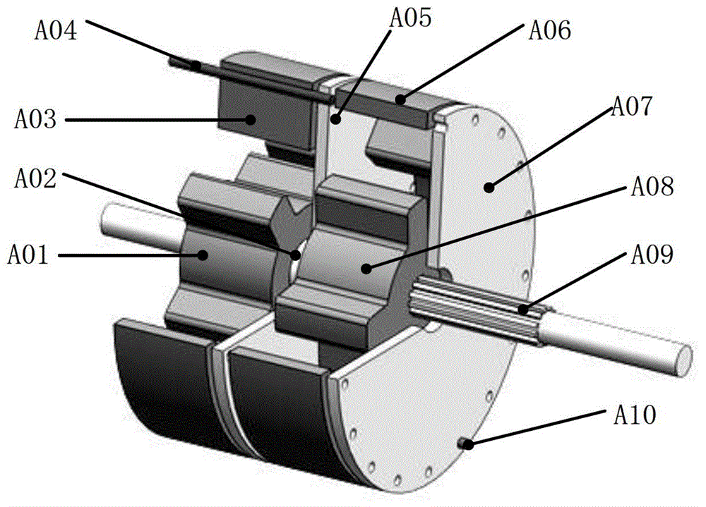
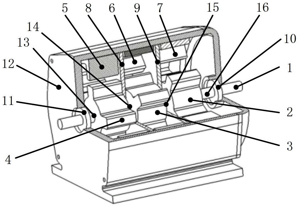
[0039] like image 3 As shown, this embodiment is a three-segment three-phase 6 / 4 type segmented switched reluctance motor, including: a main shaft 1, three-segment stators 2, 3, 4, and three-segment rotors 5, 6, 7 arranged on the main shaft 1 , and shaft sleeves 13, 14, 15, 16, wherein: two magnetic isolation plates 8, 9 are respectively provided between the first to third stators 2, 3, 4 and the first to third rotors 5, 6, 7 , The first to third rotors 5, 6, 7 are axially positioned by four sleeves 14, 15, 16, 17. The first to third stators 2, 3, 4 and the first to third rotors 5, 6, 7 are uniformly distributed around the axial direction of 360°, that is, the difference between the first to third stators 2, 3, 4 is 20°, The difference between the first to the third rotors 5, 6, 7 is 30°.

[0040] The main shaft 1 is arranged on a motor housing 12 by a rear end bearing 10 and a front end bearing 11 .

[0041] The first to third stators 2 , 3 , 4 are respectively fixed on t...

Embodiment 2

[0054] like Figure 8 As shown, the present embodiment is a four-stage 6 / 4 type segmented switched reluctance motor, including: a main shaft 601, four-stage stators 602, 603, 604, 605, four-stage rotors 606, 607, 608, 609, and shaft sleeves 610, 611, 612, 613, 614, wherein: each section of stator 602, 603, 604, 605 and each section of rotor 606, 607, 608, 609 are respectively provided with magnetic isolation plates 615, 616, 617, the rotors 606, 607, 608, 609 of each section are axially positioned by the shaft sleeves 610, 611, 612, 613, 614. Each section of stator 602, 603, 604, 605 and rotor 606, 607, 608, 609 are uniformly distributed around the axial direction of 360°, that is, the difference between each section of stator 602, 603, 604, 605 is 15°, and each section of rotor 606, The difference between 607, 608, and 609 is 22.5°.

[0055] The main shaft 601 is a spline shaft, and is arranged on the motor housing 620 by the rear end bearing 618 and the front end bearing 6...

Embodiment 3

[0058] like Figure 10 As shown, this embodiment is a two-stage 8 / 6 type segmented switched reluctance motor, including: a main shaft 713, two-stage stators 708, 709, two-stage rotors 710, 711 arranged on the main shaft 713, and a shaft sleeve 704 , 705, 706, wherein: a magnetic isolation plate 712 is provided between the stators 708, 709 and the rotors 710, 711, and the rotors 710, 711 are axially positioned by the sleeves 704, 705, 706. The phase difference between the stators 708, 709 is 22.5°, and the phase difference between the rotors 710, 711 is 30°.

[0059] The main shaft 713 is a spline shaft, and the rear end bearing 704 and the front end bearing 703 are arranged on the motor housing 701, the magnetic isolation plate 712 is fixed on the motor housing 713 by tightening screws, and the stator 708 is fixed by bolts 707 On the motor housing 701 and the magnetic isolation plate 712 , the side of the stator 709 is fixed on the magnetic isolation plate 712 and the other s...


PUM


Abstract

The invention discloses a sectional type switch reluctance motor, belonging to the field of magnetic circuit components. The sectional type switch reluctance motor comprises a main shaft, at least two sections of stators, at least two sections of rotors and magnetic isolating plates arranged on the main shaft, wherein each section of the stators and each section of the rotors are respectively provided with magnetic isolating plates, and each section of the stators and each section of the rotors are uniformly distributed around 360 degrees in the axial direction respectively. Stator poles of each phase of each section of the stators are respectively connected in series and are connected with a one-way guide circuit; the one-way guide circuit comprises four rectifier diodes, energy storage capacitors, main control thyristor switches and guide thyristor switches which are connected in series two by two; series circuits of each stator pole are mutually connected in parallel; one ends of the series circuits are respectively connected with the main control thyristor switches and guide thyristor switches; and the middles of two series circuits of the rectifier diodes are respectively connected with two output ends of the alternative current. By utilizing the sectional type switch reluctance motor, output torque pulse can be effectively reduced, and by guiding the induced current among the sections, the energy consumption efficiency of a system is improved, the impact of the induced current to the components is reduced, and the service life of the system is prolonged.

Description

technical field [0001] The invention relates to the field of magnetic circuit components, in particular to a segmented switched reluctance motor. Background technique [0002] The switched reluctance motor (Switched Reluctance Motor, SRM) originated from the reluctance motor in the 1940s. The invention and use of high-power thyristors made the switched reluctance motor widely used. According to the summary of American scholar S.A.Nasar, the main characteristics of switched reluctance motors are switching and reluctance. Switching means that the motor must work in a continuous switching mode; reluctance means that it is a double salient pole motor, and the stator and rotor have variable reluctance circuits. Its main advantages are: simple motor structure, low cost, high-speed operation; each phase works independently, high system reliability; simple power circuit, safe and reliable. Because of these advantages, switched reluctance motors have been widely used in electric ve...

Claims


Application Information

Patent Timeline
IPC IPC(8): H02K16/00
Inventor 刘成良王双园李炳初贡亮凌晓李彦明
Owner 费赛恩流体技术(合肥)有限公司
Why Eureka
Try Eureka