
Direct-embedded electronic equipment protection device and direct-embedded optical-cable communication access equipment

A technology for electronic equipment and protection devices, applied in the direction of sealed casings, fiber mechanical structures, etc., can solve problems such as being susceptible to man-made damage, occupying land resources, affecting traffic, etc., to overcome water leakage, ensure smooth communication, and prevent water condensation. Effect

Inactive Publication Date: 2012-07-18
CHINA MOBILE GRP GUANGDONG CO LTD
View PDF4 Cites 1 Cited by
  • Summary
  • Abstract
  • Description
  • Claims
  • Application Information

AI Technical Summary

Problems solved by technology

[0009] The purpose of the present invention is to overcome the deficiencies of the prior art, and provide a direct-buried electronic equipment protection device and direct-buried optical cable communication access equipment, which solves the problem of occupying land resources, affecting city appearance, affecting traffic, and easily The problem of man-made damage, and deepen the coverage of optical cable network, save pipeline resources, speed up the construction response speed, accelerate the comprehensive coverage, and create construction conditions for many areas limited by objective conditions

Method used


Image

  • Direct-embedded electronic equipment protection device and direct-embedded optical-cable communication access equipment
  • Direct-embedded electronic equipment protection device and direct-embedded optical-cable communication access equipment
  • Direct-embedded electronic equipment protection device and direct-embedded optical-cable communication access equipment

Examples


Embodiment Construction

[0050] In order to fully understand the technical content of the present invention, the technical solutions of the present invention will be further introduced and illustrated below in conjunction with specific examples, but not limited thereto.

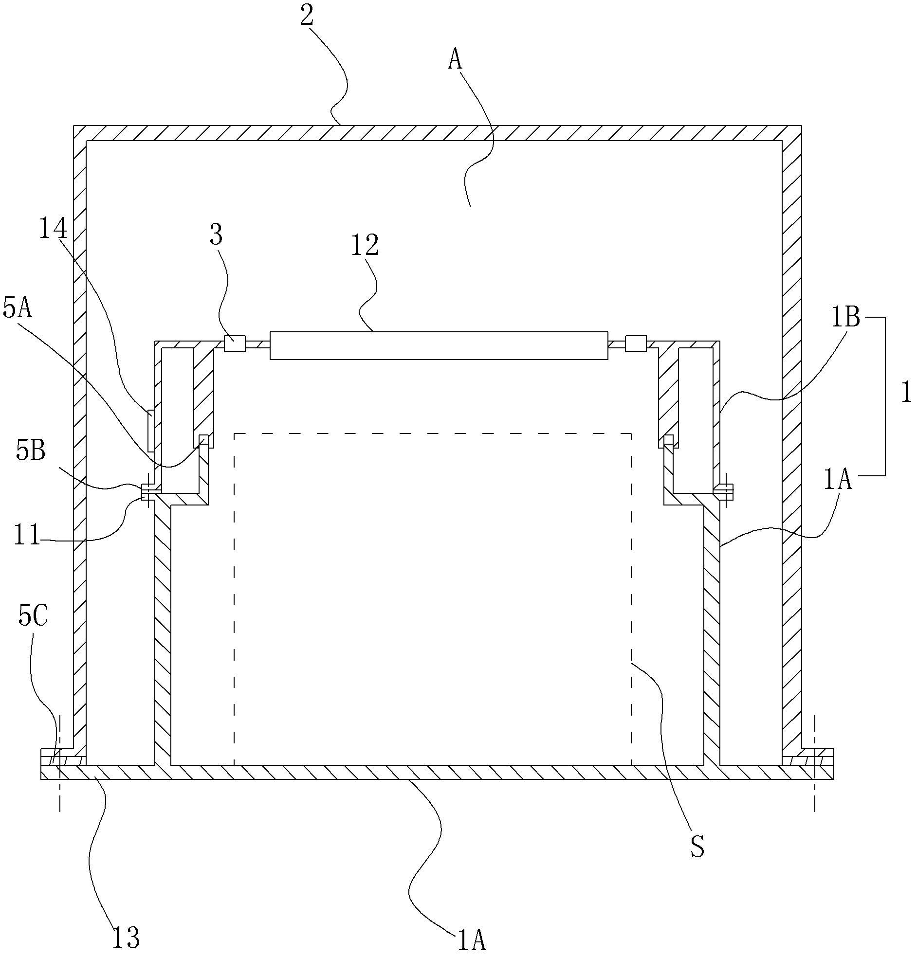
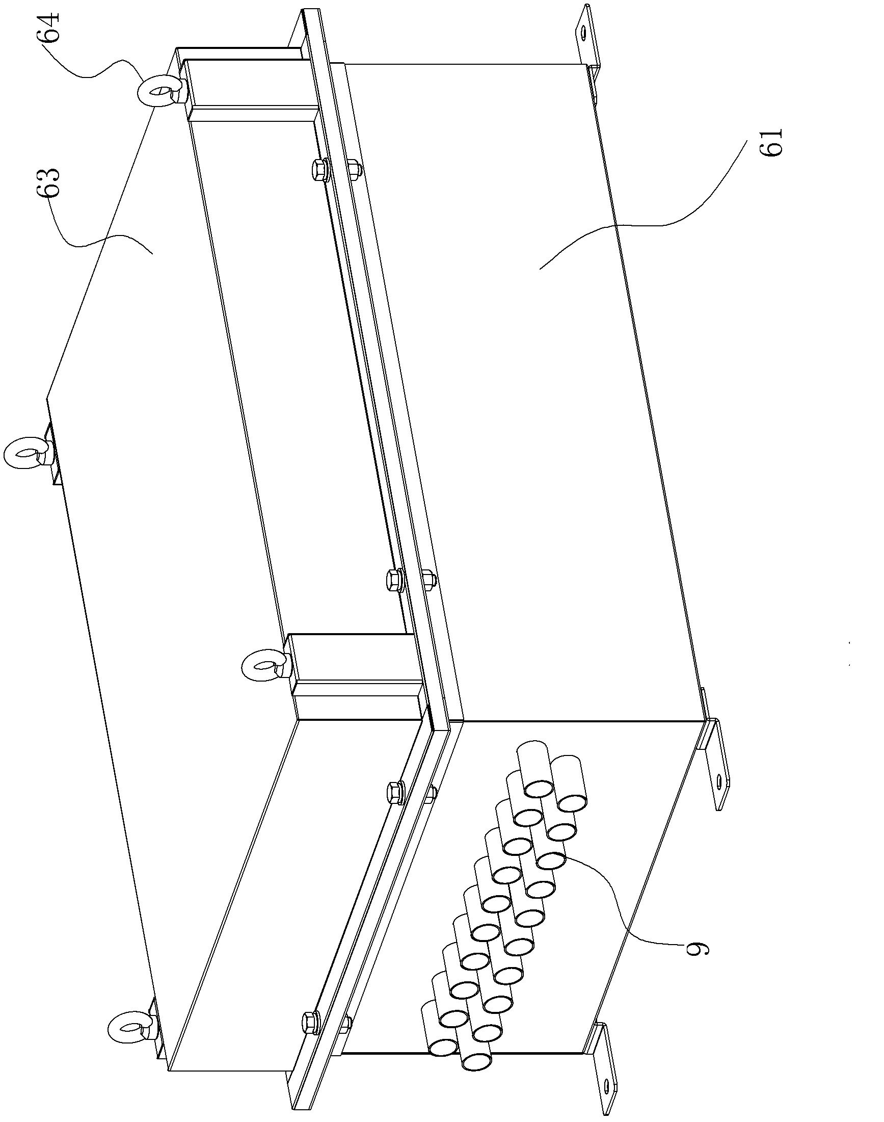
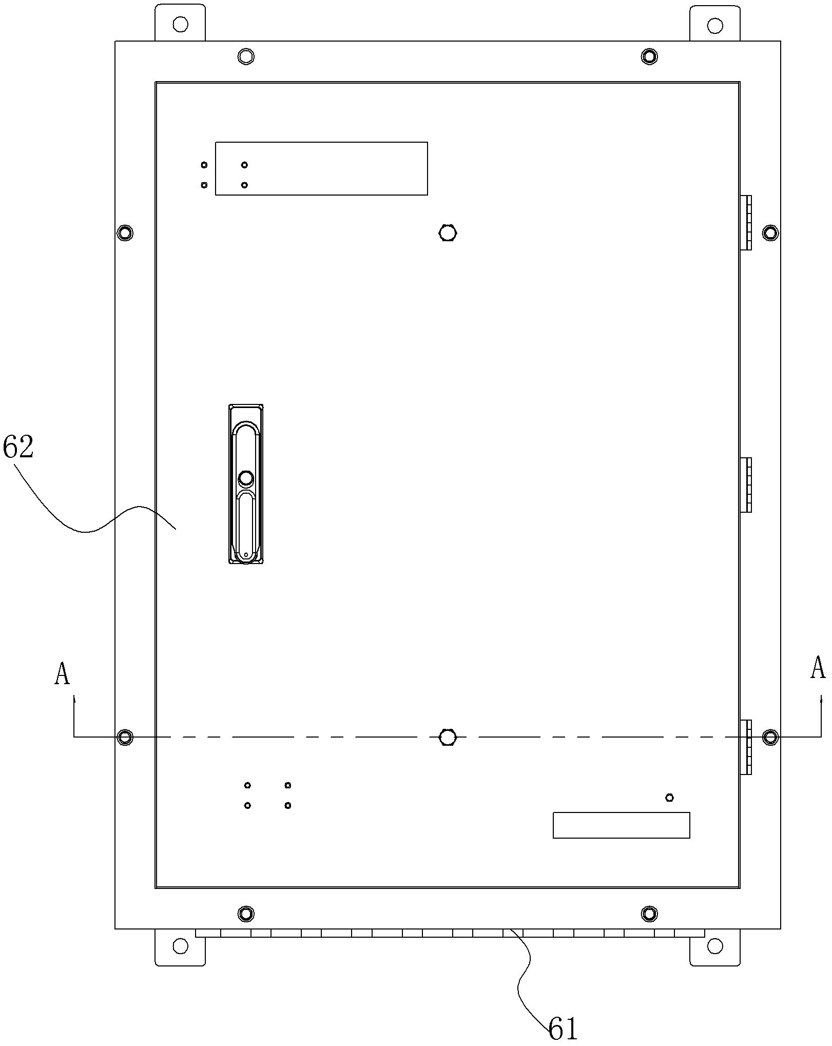
[0051] Such as figure 1 As shown, it is a structural schematic diagram of the direct-buried electronic equipment protection device of the present invention, which includes a protective casing 1 of the direct-buried electronic equipment S, and also includes an isolation cover 2 arranged above the protective casing 1, and the protective casing 1 An air isolation space A is provided between the upper part and the isolation cover 2; the protective shell 1 is provided with a sealing edge 11 and a man-machine interface 12 located in the air isolation space A, and the isolation cover 2 is a sealing device with an opening located below. cover. All of the protective housing 1 is built in the isolation cover 2, and the surroundings of the low...


PUM


Abstract

The invention discloses a direct-embedded electronic equipment protection device and a direct-embedded optical-cable communication access equipment. The direct-embedded electronic equipment protection device comprises a protective housing of direct-embedded electronic equipment, and further comprises a shielding case arranged above the protective housing, wherein an air shielding space is formed between the upper part of the protective housing and the shielding case; the protective housing is provided with a sealing edge and / or a human-computer interface positioned in the air shielding space; and the shielding case is a sealed cover provided with an open cavity at the lower part. The protection device adopts a shielding case structure with the air shielding space and the multilayer sealing structure to take an IP68-grade sealing effect, and adopts a ventilated respirator to effectively ensure air circulation in the electronic equipment tank and prevent water in the tank from condensation. The problems of groundwater immersion, water leakage of the tank body and poor air circulation in the tank are effectively solved, and the functions of moisture protection, water resistance, mold prevention, salt haze prevention, dust prevention, burglary resistance, malicious damage avoidance and the like are served. The direct-embedded electronic equipment protection device can be widely used for waterproof protection of direct-embedded electronic equipment, such as direct-embedded communication equipment, direct-embedded monitoring equipment and the like.

Description

technical field [0001] The present invention relates to a protection device for electronic equipment and electronic equipment using the protection device, more specifically to a direct-buried electronic equipment protection device and a direct-buried optical cable communication access device composed of the protection device. Background technique [0002] There are several installation methods for existing optical cable transfer boxes (that is, optical cable communication access equipment): floor-mounted optical cable transfer boxes, overhead installation optical cable transfer boxes, and wall-mounted optical cable transfer boxes. There are certain space requirements, and there are quite a lot of problems in choosing the physical installation site and construction coordination. [0003] With the rapid growth of the demand for all services and the rapid increase of the requirements for the all-optical network, the functions of the existing optical cable junction boxes are con...

Claims


Application Information

Patent Timeline
Patent Type & Authority Applications(China)
IPC IPC(8): H05K5/06G02B6/44
Inventor 林辉宣朱小升
Owner CHINA MOBILE GRP GUANGDONG CO LTD
Learn More