
Combustion plate

A combustion plate and burner technology, applied in the direction of burners, burners, combustion methods, etc., can solve the problems of increased passage resistance of combustion plates, increased blower burden, increased blower noise, etc., to reduce passage resistance and opening ratio The effect of increasing and reducing the burden

Inactive Publication Date: 2012-07-18
RINNAI CORP
View PDF7 Cites 2 Cited by
  • Summary
  • Abstract
  • Description
  • Claims
  • Application Information

AI Technical Summary

Problems solved by technology

[0004] However, in the combustion panel described in Patent Document 1, since the flame holes with different diameters are arranged in a grid pattern, the opening ratio of the flame holes (the ratio of the total area of ​​all the flame holes to the total area of ​​the combustion region of the plate main body) Relatively small, in the combustion plate described in the embodiment, the opening ratio of the fire hole is about 26%
Therefore, the passage resistance of the combustion plate increases, the burden on the blower that supplies primary air to the burner increases, and the noise of the blower increases.

Method used


Image

  • Combustion plate
  • Combustion plate
  • Combustion plate

Examples


Embodiment Construction

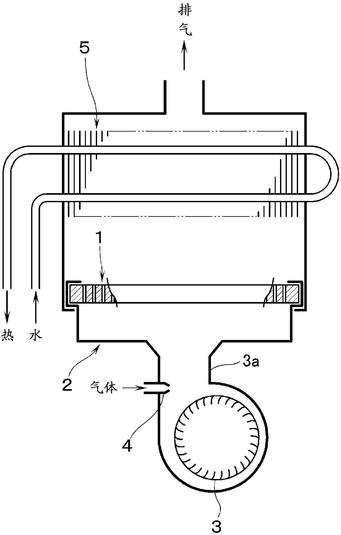
[0032] figure 1 A heat source machine for hot water supply or heating including a totally aerated combustion burner (totally aerated combustion burner) 2 using a combustion plate 1 is shown. The blower 3 is connected to the burner 2 via the ventilation passage 3a. Furthermore, a gas nozzle 4 for injecting fuel gas is provided in the ventilation passage 3a. Furthermore, the premixed gas of the primary air supplied from the blower 3 and the fuel gas injected from the gas nozzle 4 is sprayed and burned through the combustion plate 1, and the heat exchanger 5 for supplying hot water or heating is heated by the combustion gas. .

[0033] Here, the blower 3 is controlled so that the amount of primary air is larger than the stoichiometric air amount required for complete combustion of the fuel gas. Therefore, the premixed gas having an excess air ratio (primary air volume / stoichiometric air volume) greater than 1 is injected through the combustion plate 1 to perform primary total ...


PUM


Abstract

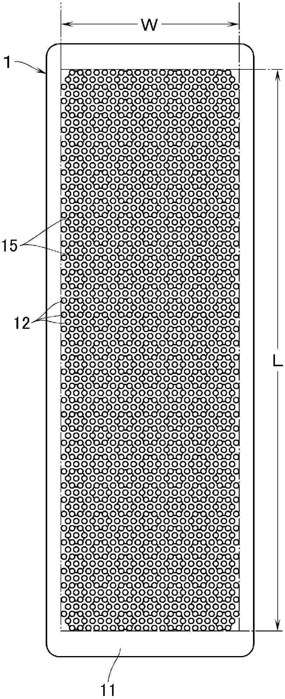
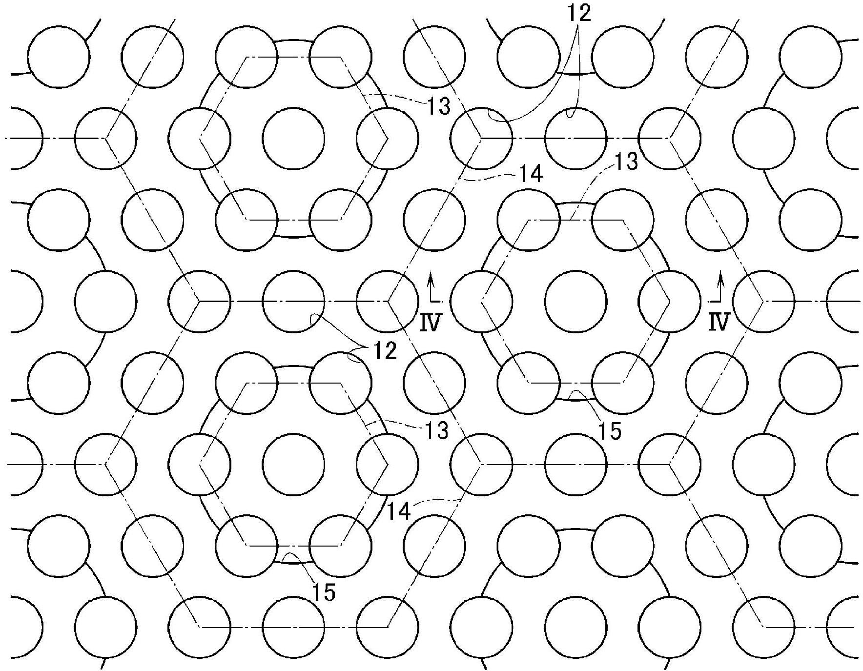
Provided is a combustion plate wherein combustion resonance or instability during high-load combustion can be overcome, and a high opening percentage for flame holes can be ensured. Flame holes (12) having the same diameter are evenly arranged over the entirety of the combustion area of a plate main body so that three adjacent flame holes are positioned so as to define an equilateral triangle. Flame hole groups, each of which is comprised of six flame holes (12) positioned so as to define a regular hexagon (13) and one flame hole (12) positioned at the center of the regular hexagon, are adjacent to each other across large regular hexagons (14), each of which surrounds a regular hexagon (13). Each of the flame hole groups is defined as a unit flame hole group, and bottomed holes (15), each of which is coaxial with the flame hole (12) positioned at the center of each unit flame hole group, are formed in the surface of the plate main body. Furthermore, if a predetermined diagonal direction or a predetermined opposing direction of the opposite sides of each regular hexagon (13) is defined as a column direction, at least one of twelve flame holes is closed, said twelve flame holes positioned on each large regular hexagon (14) surrounding each unit flame hole group that belongs to a selected column which is selected from among the columns of the unit flame hole groups arranged in the column direction and is spaced from apart from other selected columns by a predetermined distance in a direction perpendicular to the column direction.

Description

technical field [0001] The present invention mainly relates to a combustion plate used in a primary total combustion type burner installed in a heat source machine for hot water supply or heating, and a ceramic plate body is formed with a premixed gas jet. multiple fire holes. Background technique [0002] In the past, as this kind of combustion plate, Japanese Patent Document 1 has known a combustion plate as follows: three kinds of fire holes, large, medium and small, are formed in the entire combustion area of ​​the plate main body, and various fire holes are scattered into a lattice shape, and the large fire holes Located at the center of four adjacent small fire holes and at the center of four adjacent medium fire holes, each small fire hole is located in the middle of two adjacent medium fire holes, on the surface of the main body of the plate, forming A concave hole is concentric with each large fire hole and includes a part of the size of each small fire hole around...

Claims


Application Information

Patent Timeline
Patent Type & Authority Applications(China)
IPC IPC(8): F23D14/02
CPCF23D14/58F23D2210/00F23D14/34F23D2203/1023F23D14/74
Inventor 羽木敏伊藤久敏冈本英男高须芳彦
Owner RINNAI CORP
Learn More