
Air conditioner

By detecting the temperature change rate of the compressor and refrigerant to determine whether heating is required, the problem of reduced lubricating oil viscosity and power consumption caused by refrigerant accumulation during the air conditioner shutdown period is solved, and more effective power management is achieved.

Active Publication Date: 2012-07-18
MITSUBISHI ELECTRIC CORP
View PDF9 Cites 10 Cited by
  • Summary
  • Abstract
  • Description
  • Claims
  • Application Information

AI Technical Summary

Problems solved by technology

[0011] However, in Patent Document 2, the liquefaction of the refrigerant is judged based on the discharge temperature and the refrigerant saturation temperature converted from the discharge pressure, and the compressor is heated regardless of whether the lubricating oil concentration is high, which still consumes useless power. problems

Method used


Image

  • Air conditioner
  • Air conditioner
  • Air conditioner

Examples


Embodiment approach 1

[0027] (The overall structure of the air conditioner 50)

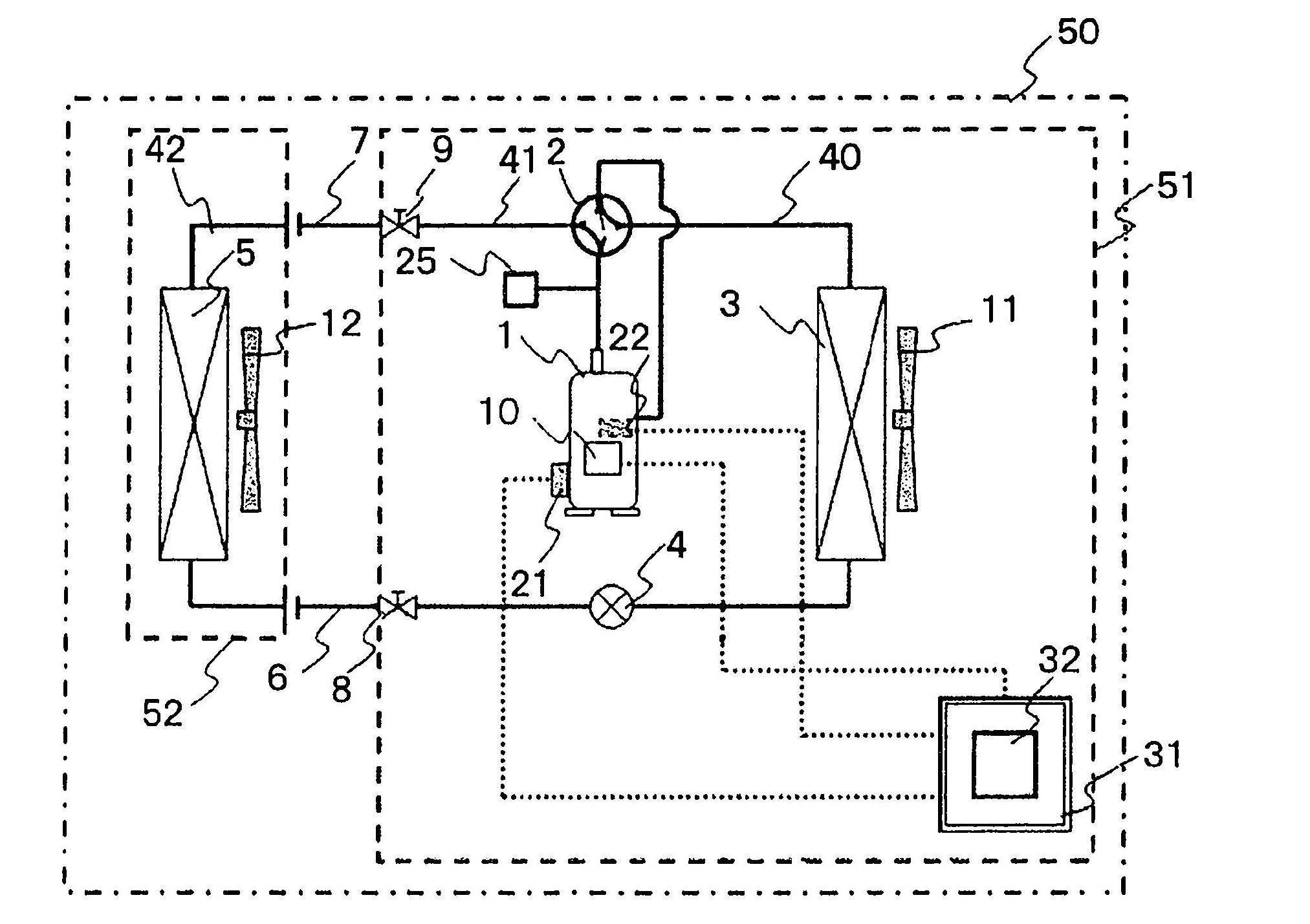
[0028] figure 1 It is an overall configuration diagram of an air conditioner 50 according to an embodiment of the present invention.

[0029] Such as figure 1 As shown, the air conditioner 50 has an outdoor unit 51 and an indoor unit 52, and has a refrigerant circuit 40 that is a circulation circuit for circulating refrigerant in the outdoor unit 51 and the indoor unit 52.

[0030] The refrigerant circuit 40 is composed of an outdoor refrigerant circuit 41 as a heat source side refrigerant circuit of the outdoor unit 51, an indoor refrigerant circuit 42 as a utilization side refrigerant circuit of the indoor unit 52, and connecting the The liquid side connection pipe 6 and the gas side connection pipe 7 of the outdoor refrigerant circuit 41 and the indoor refrigerant circuit 42 are connected.

[0031] The outdoor refrigerant circuit 41 is composed of at least the following parts: a compressor 1, a four-way valve 2, an outdoor ...

Embodiment approach 2

[0077] In the present embodiment, the description will be focused on points different from the air conditioner 50 of the first embodiment.

[0078] The configuration of the air conditioner 50 of this embodiment is the same as the configuration of the air conditioner 50 of the first embodiment.

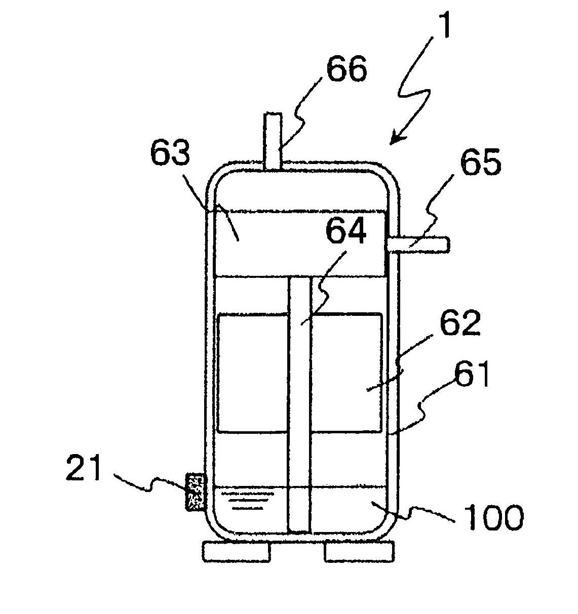
[0079] (Change with time of the state quantity of the heating operation of the compressor 1)

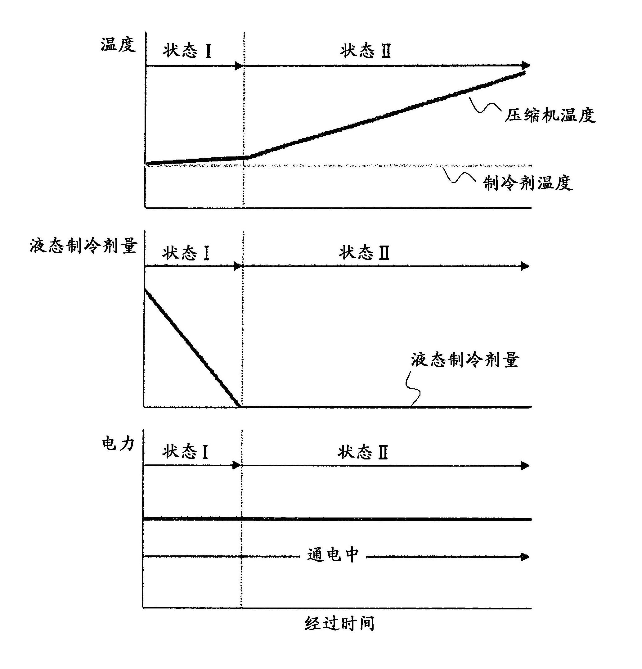
[0080] Image 6 It is a graph showing changes over time in the compressor temperature of the compressor 1, the amount of liquid refrigerant in the compressor 1, and the viscosity of the lubricating oil 100 during the stop period of the air conditioner 50 according to Embodiment 2 of the present invention.

[0081] Such as Image 6 As shown, while the air conditioner 50 is stopped, when the control device 31 heats the compressor 1 through the compressor heating unit 10, the amount of liquid refrigerant dissolved in the lubricating oil 100 in the compressor 1 is reduced due to vaporization. Then, due t...


PUM


Abstract

Provided is an air conditioner which appropriately determines accumulation of refrigerant in a compressor, and minimizes power consumption during a period when the air conditioner is stopped to operate. Upon determining that the compressor temperature change rate (Rc1) is larger than the refrigerant temperature change rate (Rr1), a control apparatus (31) determines that liquid refrigerant contained in lubricant oil (100) inside a compressor (1) has all evaporated, and stops a current from being applied to an electric motor unit (62), whereby operation for heating the compressor (1) is terminated.

Description

Technical field [0001] The present invention relates to an air conditioner having a compressor, and more particularly to the control of a mechanism for heating the compressor during an operation stop. Background technique [0002] In an apparatus equipped with a refrigeration cycle, such as an air conditioner, refrigerant may accumulate in the compressor while the apparatus is stopped. For example, like an air conditioner, when the heat exchanger as its constituent element is installed outdoors, the refrigerant stored in the compressor is dissolved in the lubricating oil in the compressor, so that the viscosity of the lubricating oil and the lubrication The oil concentration decreases together. If the compressor is started in this state, low-viscosity lubricating oil is supplied to the rotating shaft and compression part of the compressor, and there is a risk of burns due to poor lubrication. In addition, when the liquid level of the lubricating oil in the compressor rises due ...

Claims


Application Information

Patent Timeline
Patent Type & Authority Applications(China)
IPC IPC(8): F25B1/00
CPCF25B1/00F25B13/00F25B31/00F25B2400/01F25B2500/16F25B2500/19F25B2500/26F25B2500/31F25B2700/04F25B2700/193F25B2700/2105F25B2700/2106F25B2700/2115
Inventor 加藤央平齐藤信涌田尚季
Owner MITSUBISHI ELECTRIC CORP
Learn More