Optical fiber end structures for improved multi-mode bandwidth, and related systems and methods

A multi-mode optical fiber and optical fiber technology, applied in transmission systems, multi-mode transmission, optical fiber transmission, etc., can solve the problem of clock frequency reducing link transmission data rate, etc.

Inactive Publication Date: 2012-07-18
CORNING INC
View PDF5 Cites 4 Cited by
  • Summary
  • Abstract
  • Description
  • Claims
  • Application Information

AI Technical Summary

Problems solved by technology

However, reducing the clock frequency of the wavefo

Method used


Image

  • Optical fiber end structures for improved multi-mode bandwidth, and related systems and methods
  • Optical fiber end structures for improved multi-mode bandwidth, and related systems and methods
  • Optical fiber end structures for improved multi-mode bandwidth, and related systems and methods

Examples


Embodiment Construction

[0025] Referring now to the embodiments in detail, examples of which are illustrated in the accompanying drawings, in which some, but not all, are shown. The concepts may, of course, be embodied in many different forms and should not be construed as limiting herein; rather, these embodiments are provided so that this disclosure will satisfy applicable legal requirements. Wherever possible, the same reference numerals will be used to refer to the same components or parts.

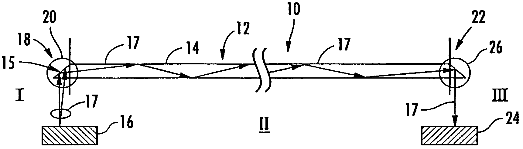
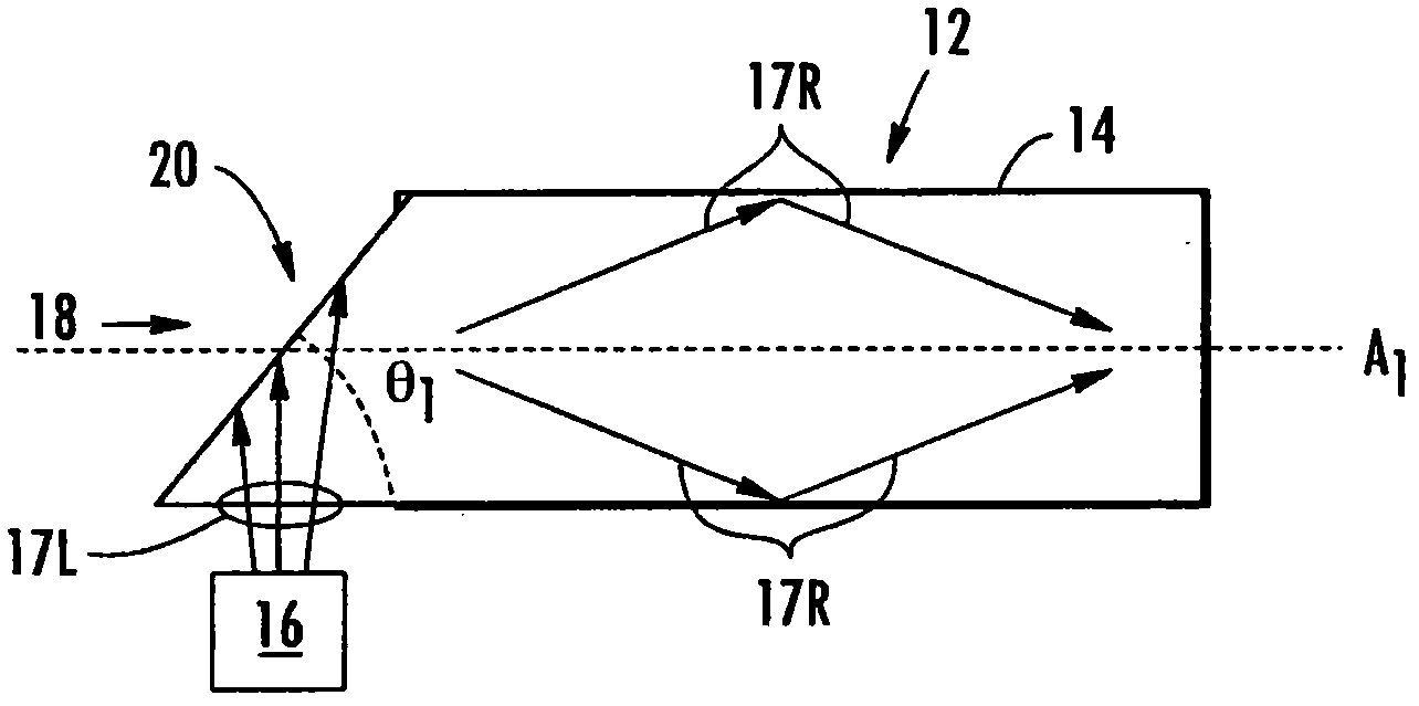
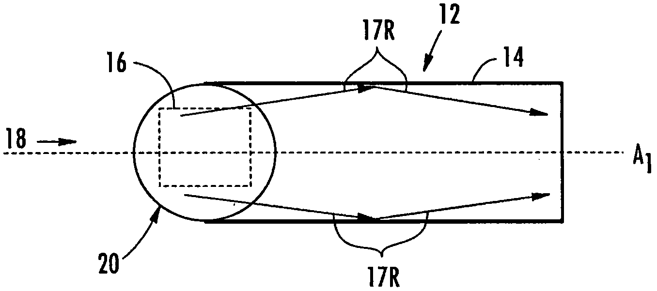
[0026] Embodiments disclosed in this detailed description include multimode fiber optic equipment, multimode fiber optics, and related methods for improving the bandwidth of fiber optic links. One or more end structures may be placed at the fiber end of a multimode fiber to improve link bandwidth by reducing and / or eliminating modal dispersion. Modal dispersion can result from fiber launch conditions that excite a set of modes or groups of modes in the fiber that have group velocities that differ significan...


PUM


Abstract

Multi-mode optical fiber apparatuses, multi-mode optical fibers, and related methods for improving fiber link bandwidth are disclosed. One or more end structures can be disposed on an optical fiber end of a multi-mode optical fiber to improve link bandwidth by reducing and/or eliminating modal dispersion. Modal dispersion can be caused by higher-order modes or modes in an optical fiber being excited by received light. Modal dispersion can limit the bandwidth of an optical fiber link. In certain embodiments, end structures for multi-mode optical fibers are disclosed for reducing the launch angle of light in an optical fiber to reduce modal dispersion. In other embodiments, end structures for multi-mode optical fibers are disclosed for reducing or eliminating coupling astigmatism. In other embodiments, end structures for multi-mode optical fibers are disclosed for directing higher order modes or groups away from an optical detector to reduce or eliminate modal dispersion. In one embodiment, a prism structure is disposed on the source end of the multi-mode optical fiber. In other embodiments a convex profile lens is disposed at the source and detector ends of the fiber.

Description

technical field [0001] The techniques of the present invention relate to multimode fiber links and the bandwidth of multimode fiber links. Background technique [0002] Optical fibers are used in a variety of applications to transport and process light. Examples include: transmitting light to or receiving light from integrated optical components or devices formed on substrates, transmitting information channels in wavelength division multiplexed optical communication devices and systems, forming fiber optic switch matrix devices or optical fiber array-to-array connector, and to generate optical gain for optical amplification or laser oscillation. Optical fibers essentially operate as "light pipes" to confine light within the boundaries of the fiber and to convey light from one point to another. [0003] The optical system may include optical elements that transmit light onto and receive light from optical fibers for optical signal transmission. Aligning the optical elemen...

Claims


Application Information

Patent Timeline
IPC IPC(8): H04B10/13G02B6/42H04B10/2581
CPCG02B6/4202G02B6/4214G02B6/43H04B10/2581
Inventor 杰弗里·艾伦·德梅里特安德列·叶夫根尼耶维奇·科罗廖夫弗拉迪米尔·尼科拉耶维奇·纳扎罗夫詹姆斯·斯科特·萨瑟兰
Owner CORNING INC
Why Eureka
Try Eureka