Sewage filter plant

A filter device and sewage technology, applied in the direction of filtration and separation, fixed filter elements, chemical instruments and methods, etc., can solve the problems of clogged filters, energy loss, complex structure, etc., to avoid accumulation of dirt, simple structure, Effects that are handled in a simple way

Inactive Publication Date: 2012-07-25
SOUTHEAST UNIV
View PDF4 Cites 44 Cited by
  • Summary
  • Abstract
  • Description
  • Claims
  • Application Information

AI Technical Summary

Problems solved by technology

There are three major disadvantages: first: complex structure, high cost, and large power consumption (using water pump to flush); second: the dirt after flushing remains in t

Method used


Image

  • Sewage filter plant
  • Sewage filter plant
  • Sewage filter plant

Examples


Embodiment Construction

[0020] The technical solutions of the present invention will be described in detail below in conjunction with the accompanying drawings, but the protection scope of the present invention is not limited to the embodiments.

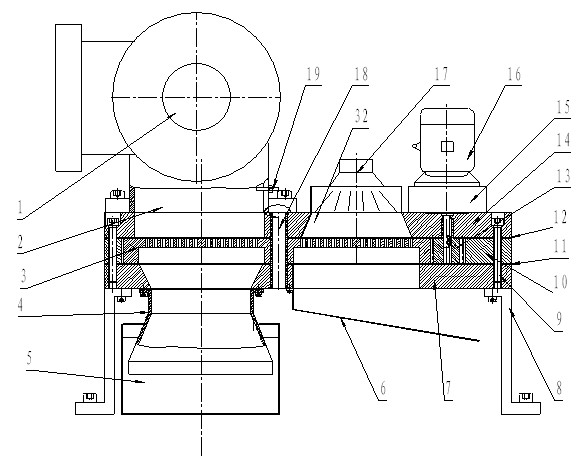
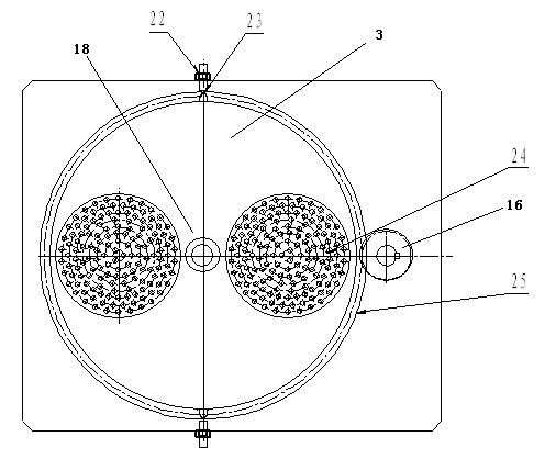
[0021] The sewage filtering device of the present invention comprises a support 8, a water inlet 4, a turntable 3, a rotating shaft 18, a water flushing sprinkler 17, a drive motor 16 and a reducer 15; the support 8 is provided with an upper support plate 14 and a lower support plate 7 , the rotating disk 3 is horizontally arranged between the upper supporting plate 14 and the lower supporting plate 7, the rotating shaft 18 passes through the axis of the rotating disk 3, and the upper and lower ends of the rotating shaft 18 are respectively arranged on the upper supporting plate 14 and the lower supporting plate 7; 2 corresponds to the water inlet 4 up and down, and is arranged on the upper support plate 14 and the lower support plate 7 respectively. The lo...


PUM


Abstract

The invention discloses a sewage filter plant, which comprises a support, a water inlet channel, a rotating disc, a rotating shaft, a water scouring sprayer, a driving motor and a speed reducer. Two filters capable of switching are arranged on a suction opening pipeline of a water pump, a pressure sensor automatically detects a water pressure setting value, when blocked, a filter screen is automatically replaced and cleaned, the total process is finished instantly, and the water pump does not stop. The sewage filter plant has the advantages of simple structure, low cost and power consumption, capabilities of effectively avoiding blockage due to dirt and guaranteeing stable operation of a system, and the like.

Description

technical field [0001] The invention belongs to the field of sewage treatment equipment and relates to a sewage solid matter filtering device. Background technique [0002] Urban sewage is an excellent and eye-catching "cold / heat source". The heat (cold) energy stored in urban sewage discharge can be utilized through heat pump technology to meet the needs of building air conditioning and domestic hot water to achieve energy conservation and emission reduction. For purposes, the system is called a sewage source heat pump system. [0003] During the use of the sewage source heat pump system, the sewage must be strictly filtered to reach the state required by the heat pump heat exchange device. The composition of urban sewage is complex, and the size span of the dirt is large. It is easy to accumulate scale in the heat exchanger and block the filter screen. The dirt is usually corrosive and will damage the equipment if it is not removed in time. Once the heat exchange equipme...

Claims


Application Information

Patent Timeline
IPC IPC(8): B01D29/96B01D29/03
Inventor 杨涛张小松
Owner SOUTHEAST UNIV
Why Eureka
Try Eureka