
Welding screw moulding die

A technology for forming molds and screws, applied in the directions of forming tools, manufacturing tools, metal processing equipment, etc., can solve the problems such as the failure of the bolt bonding surface and the installation part to closely fit, the inability to play a waterproof role, and the reduction of welding reliability. To achieve the effect of simple structure, improve work efficiency and reduce waste

Inactive Publication Date: 2012-07-25
苏州新凌电炉有限公司
View PDF0 Cites 0 Cited by
  • Summary
  • Abstract
  • Description
  • Claims
  • Application Information

AI Technical Summary

Problems solved by technology

[0002] Commonly produced welding screws have two types: penetrating and non-penetrating. The traditional penetrating screw only has the basic function of its installation and fastening. Due to its structural limitations, when the bolt is welded to the installation part, the bolt The fitting surface and the installation part cannot be tightly fitted
This is because its welding surface is usually designed as three bosses, which are staggered from each other at intervals of 120 degrees. There are relatively obvious gaps, and foreign substances including water and dust penetrate into the screw side of the penetrating bolt through these gaps, and flow along the direction of the screw, so it cannot play a waterproof role
In addition, because the three bosses are disconnected, the force is uneven, which reduces the reliability of welding; the connection area is limited, which also affects its bearing capacity

Method used


Image

  • Welding screw moulding die
  • Welding screw moulding die
  • Welding screw moulding die

Examples


Embodiment Construction

[0011] The present invention is described below in conjunction with accompanying drawing.

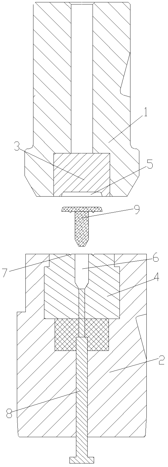
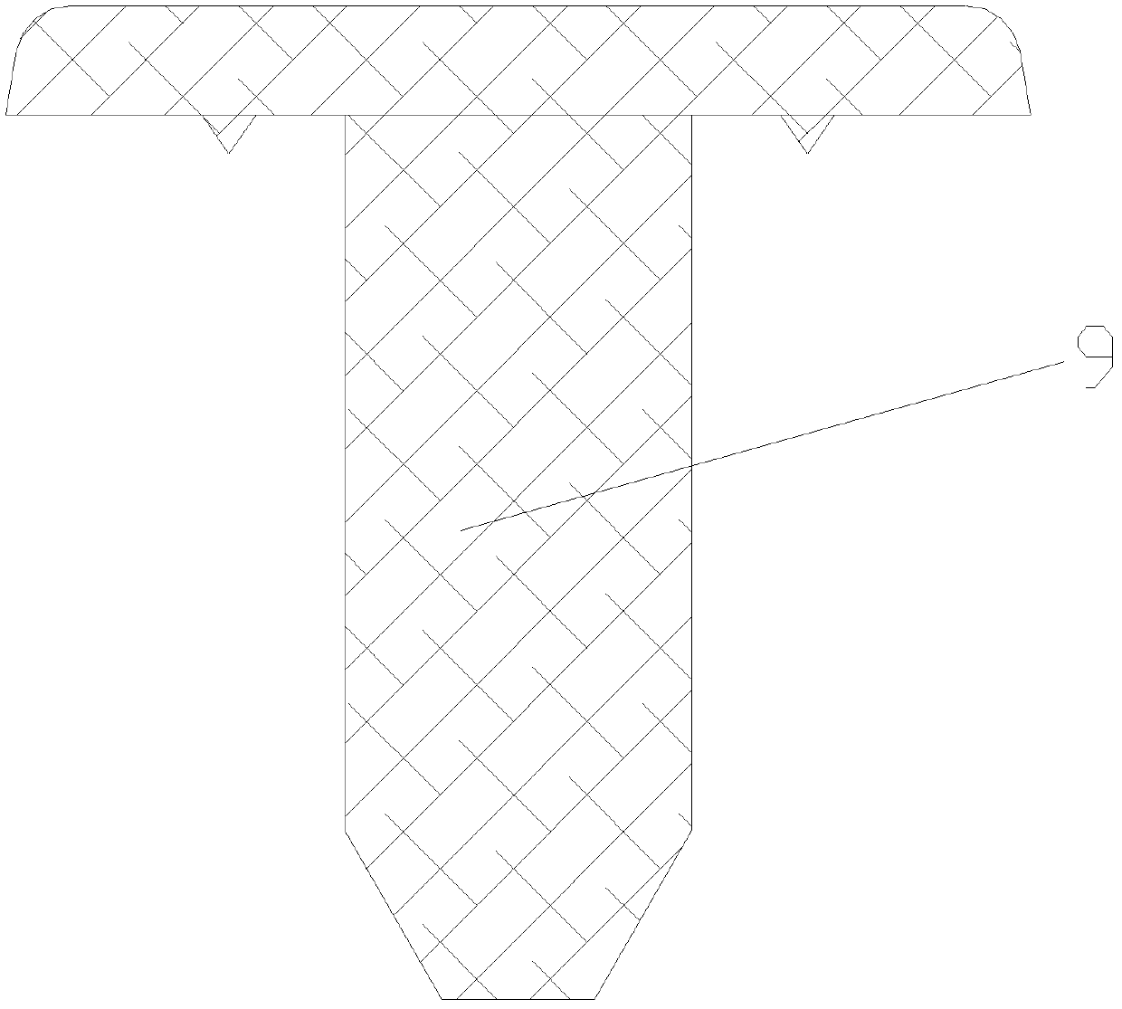
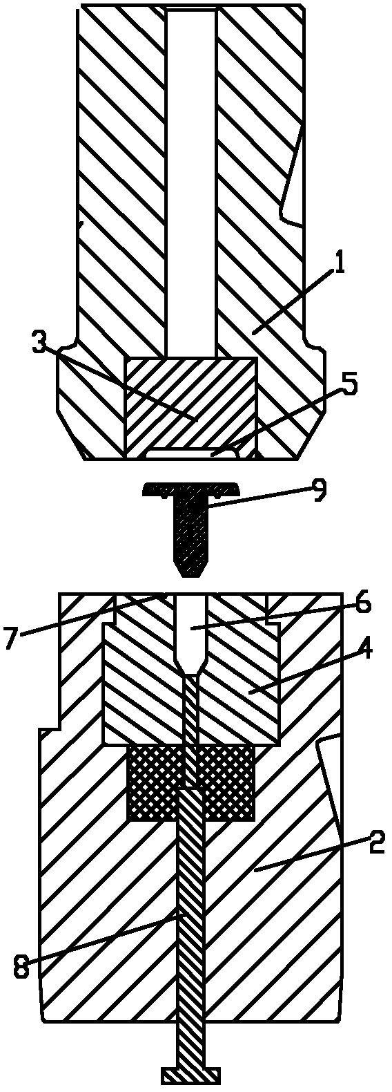
[0012] attached figure 1 , 2 It is a kind of welding screw molding die according to the present invention, comprising an upper mold 1, a lower mold 2 and a product ejection pin 8 arranged in the lower mold 2, the upper mold 1 is provided with an upper mold core 3; There is a screw head molding cavity 5 at the bottom of the mold core 3; a lower mold core 4 is arranged inside the lower mold; a screw shank forming cavity 6 is arranged inside the lower mold core 4; the bottom of the screw shank forming cavity 6 is It is a conical cavity; the end surface of the lower mold core 4 is provided with an annular groove 7; the cross section of the annular groove 7 is V-shaped.

[0013] The above-mentioned embodiments are only to illustrate the technical conception and characteristics of the present invention. Substantial equivalent changes or modifications shall fall within the protection scope ...


PUM


Abstract

The invention discloses a welding screw moulding die which comprises an upper die, a lower die and a product ejecting pin arranged in the lower die. The upper die is internally provided with an upper die core. A screw head moulding cavity is formed at the bottom of the upper die core. The lower die is provided with a lower die core which is internally provided with a screw rod moulding cavity. The screw rod moulding cavity is provided with a cone-shaped cavity at the bottom. A circular groove is further arranged on the end surface of the lower die core. The cross section of the circular groove is in a V-shaped structure. The welding screw moulding die provided by the invention has a simple structure. The cavity structures of the upper and lower die cores are matched to use and the circular groove in the V-shaped structure is formed on the end surface of the lower die core so as to punch the welding screw that is waterproof, uniform in stress and high in bearing capacity. With the adoption of the die, the machining step is omitted, the work efficiency is improved, the waste on raw materials is reduced and the production cost is lowered.

Description

technical field [0001] The invention relates to a mold, in particular to a welding screw forming mold. Background technique [0002] Commonly produced welding screws have two types: penetrating and non-penetrating. The traditional penetrating screw only has the basic function of its installation and fastening. Due to its structural limitations, when the bolt is welded to the installation part, the bolt The fitting surface and the installation part cannot be tightly fitted. This is because its welding surface is usually designed as three bosses, which are staggered from each other at intervals of 120 degrees. There are relatively obvious gaps, and foreign substances including water and dust penetrate into the screw side of the penetrating bolt through these gaps, and flow along the screw direction, so it cannot play a waterproof role. In addition, since the three bosses are disconnected, the force is not uniform, which reduces the reliability of welding; the connection area...

Claims


Application Information

Patent Timeline
IPC IPC(8): B21D37/10B21D22/02
Inventor 张加成
Owner 苏州新凌电炉有限公司
Learn More