
Automatic riveting device

A riveting device and rivet technology are applied in the field of automatic rivet riveting devices for cold extrusion of steel plates, which can solve the problems of difficult threaded holes for thin and light steel plates, low work efficiency, and complicated operations, and achieve low manufacturing costs, simplify work, and improve production. The effect of efficiency

Inactive Publication Date: 2012-07-25
SUZHOU CHIEN SHIUNG INST OF TECH
View PDF9 Cites 2 Cited by
  • Summary
  • Abstract
  • Description
  • Claims
  • Application Information

AI Technical Summary

Problems solved by technology

[0002] In mechanical production, it is often necessary to connect a screw to the steel plate to connect the steel plate with other parts. However, many steel plates currently used are very light and thin. If threaded connections are used, it is difficult to drill threaded holes in light and thin steel plates. Rivets are used to connect the screw rods. However, since rivets are generally semi-automated, workers are required to add rivets to the mold after finishing each one. The work efficiency is low and the operation is cumbersome.

Method used


Image

  • Automatic riveting device
  • Automatic riveting device
  • Automatic riveting device

Examples


Embodiment

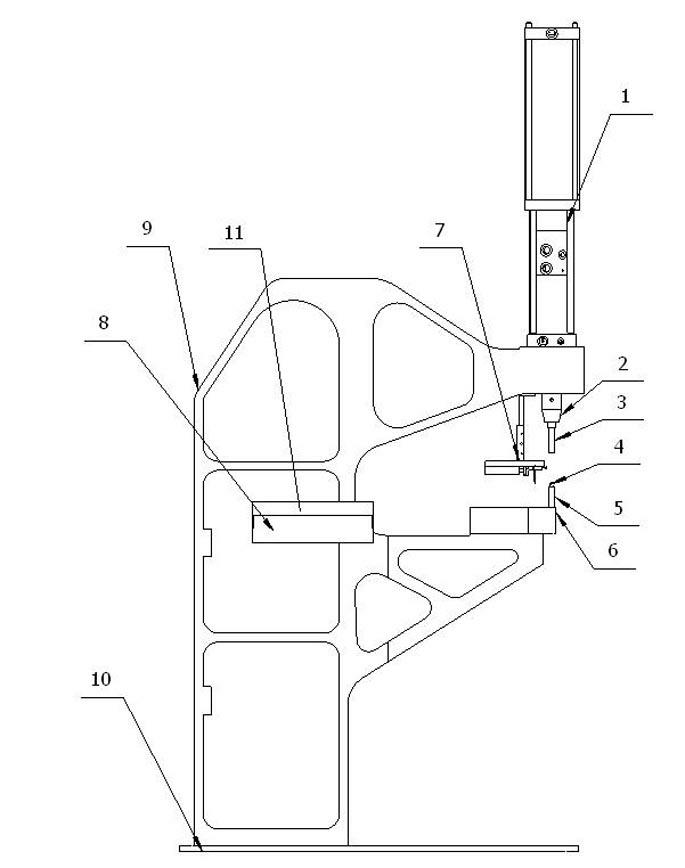
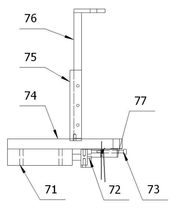
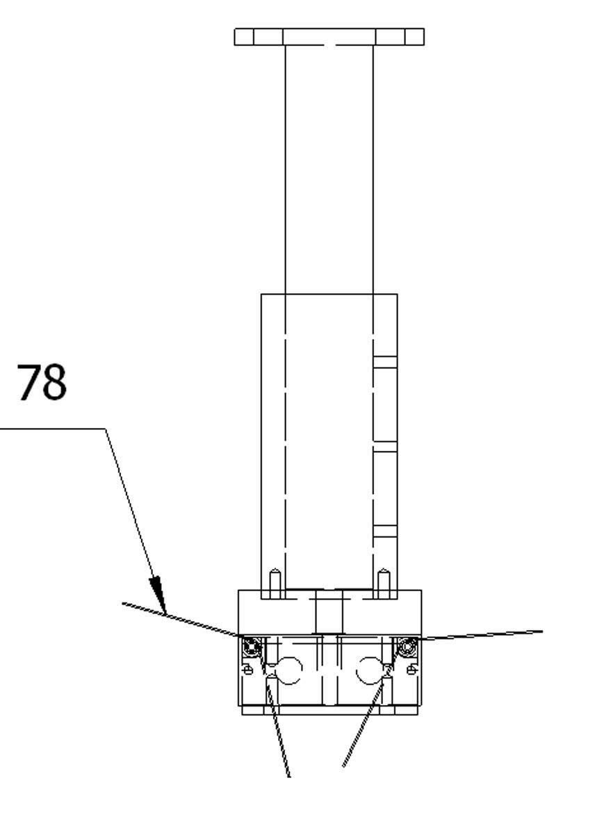
[0017] Such as Figure 1-4 A kind of automatic rivet riveting device shown, this automatic rivet riveting device comprises: booster cylinder 1, transition head 2, pressure head 3, core 4, lower mold 5, lower mold base 6, nail feeding device 7, support 8. Bed body 9, base 10 and vibrating plate 11; the nail feeding device 7 includes: cylinder 71, feeding moving seat 72, rotating screw 73, cylinder seat 74, adjustable groove plate 75, connecting plate 76, rotating door 77 , Spring 78, cylinder block 74 is provided with drop hole 79.

[0018] The connections of the above components are as follows:

[0019] The bed body 9 is fixed on the base 10, a support 8 is fixed on the bed body 9, a vibrating plate 11 is fixed above the support 8, and one end opening of the vibrating plate 11 is connected with the nail feeding device 7; the upper end of the bed body 9 is fixed to pressurize Cylinder 1 cylinder body, transition head 2 is installed at the lower end of booster cylinder 1, inde...


PUM


Abstract

The invention discloses an automatic riveting device, which comprises a pressurizing cylinder, a transition head, a pressure head, a core, a lower die, a lower die holder, a rivet feeding device, a support, a bed, a base and a vibration disk. The bed is fixed onto the base, the support is fixed onto the bed, the vibration disk is fixed onto the support, an opening at one end of the vibration disk is connected with the rivet feeding device, a pressurizing cylinder body is fixed to the upper end of the bed, the transition head is mounted at the lower end of the pressurizing cylinder, the pressure head is mounted at the lower end of the transition head, the rivet feeding device is mounted on one lower side of the pressure head, the lower die is arranged under the pressure head, the core is arranged on the lower die and is opposite to the pressure head, the lower die is fixed onto the lower die holder, and the lower die holder is mounted on the bed. The automatic riveting device is simple in structure, reliable in operation and low in manufacturing cost.

Description

technical field [0001] The invention relates to a rivet riveting device, in particular to a steel plate cold extrusion automatic rivet riveting device. Background technique [0002] In mechanical production, it is often necessary to connect a screw to the steel plate to connect the steel plate with other parts. However, many steel plates currently used are very light and thin. Rivets are used to connect the screws. However, since rivets are generally semi-automated, workers are required to add rivets to the mold after finishing each one. The work efficiency is low and the operation is cumbersome. Contents of the invention [0003] Purpose of the invention: The purpose of the invention is to solve the deficiencies of the prior art and provide an automatic rivet riveting device that does not need to manually add rivets. [0004] Technical solution: In order to achieve the above objectives, an automatic rivet riveting device according to the present invention includes: a pre...

Claims


Application Information

Patent Timeline
Patent Type & Authority Applications(China)
IPC IPC(8): B21J15/32
Inventor 阚子振杨宣飞王洪磊许红伍吴传山
Owner SUZHOU CHIEN SHIUNG INST OF TECH
Learn More