Clamping device for ring-like parts in milling
A milling processing and clamping device technology, applied in positioning devices, metal processing equipment, metal processing machinery parts, etc. Equal problems, to achieve the effect of easy control of processing size, elimination of vibration, and easy control of pressure
- Summary
- Abstract
- Description
- Claims
- Application Information
AI Technical Summary
Problems solved by technology
Method used
Image

Examples
Embodiment 1
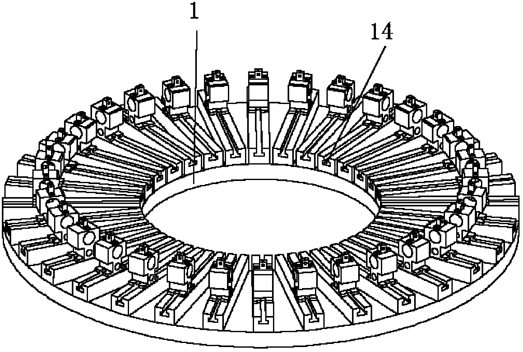
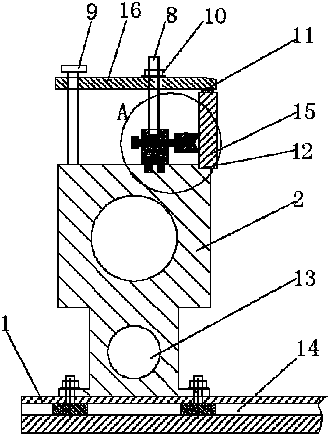
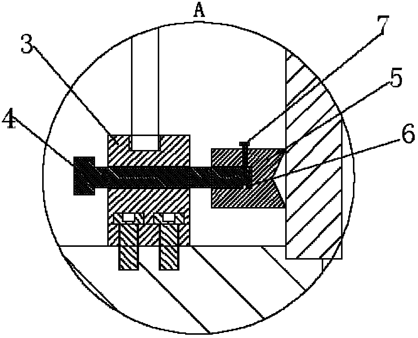
[0022] Refer to attached figure 1 to attach image 3 The shown clamping device for milling of ring parts includes a turntable 1 and 32 positioning units arranged circularly on the turntable 1, each positioning unit includes a contour block 2 and a The positioning mechanism on the cushion block 2, the positioning mechanism includes an adjustment support seat 3 fixedly connected with the contour block 2 and a radial positioning assembly for radially positioning the workpiece 15 arranged on the adjustment support seat 3 and for An axial pressing assembly for axially pressing the workpiece 15 . In order to facilitate the adjustment of the radial pressure of the radial positioning assembly on the workpiece 15, the radial positioning assembly includes a first adjustment bolt 4 passing through the adjustment support block horizontally and a radial adjustment block arranged at the end of the first adjustment bolt 4 5. The first adjusting bolt 4 is threadedly matched with the adjusti...
Embodiment 2
[0024] In the aforementioned solution, in order to make the radial adjustment block 5 move forward and backward along the direction of the first screw when the first adjustment bolt 4 rotates, and at the same time the radial adjustment block 5 will not follow the first screw to rotate, avoiding the radial adjustment block 5 Friction with the workpiece 15, the end of the first adjusting bolt 4 is provided with an annular groove 6, the radial adjustment block 5 is provided with a stop screw 7 corresponding to the annular groove 6, and the end of the stop screw 7 extends to the ring In the slot 6 , the first adjusting bolt 4 can freely rotate relative to the radial adjusting block 5 . Further, in order to prevent the radial adjustment block 5 from causing damage to the surface of the workpiece 15 when pressing the workpiece 15, the radial adjustment block 5 is made of soft metal, and usually the radial adjustment block 5 is made of copper Yes, in order to increase the contact sur...
Embodiment 3
[0026] On the basis of Embodiment 1, in order to enable the axial compression assembly to perform good axial positioning on the workpiece 15, the axial compression assembly includes a second adjustment bolt 8 arranged on the adjustment support block, and The axial pressure plate 16 with which the second adjustment bolt 8 is threaded and the third adjustment bolt 9 arranged at the outer end of the axial pressure plate 16, the third adjustment bolt 9 is threaded with the axial pressure plate 16, and the second adjustment bolt 8 is provided with The lock nut 10, the second adjusting bolt 8, the third adjusting bolt 9 and the axial pressure plate 16 are combined into a lever mechanism, and the pressing force on the workpiece 15 can be realized by adjusting the second adjusting bolt 8 and the third adjusting bolt 9, The contact between the adjustment bolt and the workpiece 15 is avoided, and the damage to the workpiece 15 is minimized. Further, in order to avoid damage to the surfa...
PUM
 Abstract
Description
Claims
Application Information
 - Generate Ideas
- Intellectual Property
- Life Sciences
- Materials
- Tech Scout
- Unparalleled Data Quality
- Higher Quality Content
- 60% Fewer Hallucinations
Browse by: Latest US Patents, China's latest patents, Technical Efficacy Thesaurus, Application Domain, Technology Topic, Popular Technical Reports.
© 2025 PatSnap. All rights reserved.Legal|Privacy policy|Modern Slavery Act Transparency Statement|Sitemap|About US| Contact US: help@patsnap.com