Supercharge Your Innovation With Domain-Expert AI Agents!

Polyurethane mixing device

A mixing device and polyurethane technology, which is applied in the field of polyurethane mixing devices, can solve the problems of inconvenient cleaning, large contact area, and many raw material residues, and achieve the effects of convenient cleaning, uniform mixing, and less raw material residues

Inactive Publication Date: 2012-07-25
王汉力
View PDF4 Cites 3 Cited by
  • Summary
  • Abstract
  • Description
  • Claims
  • Application Information

AI Technical Summary

Problems solved by technology

When cleaning, the cleaning agent is introduced from the water inlet, and the cleaning agent enters the inner cavity of the mixing cylinder. However, due to the large contact area between the mixing impeller and the raw materials, there are many raw materials remaining on the mixing impeller after the mixing is completed, and cleaning is very difficult. convenient

Method used


Image

  • Polyurethane mixing device
  • Polyurethane mixing device
  • Polyurethane mixing device

Examples


Embodiment Construction

[0010] The present invention will be further described in detail below in conjunction with the accompanying drawings and preferred embodiments.

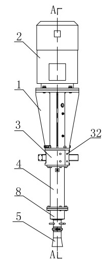
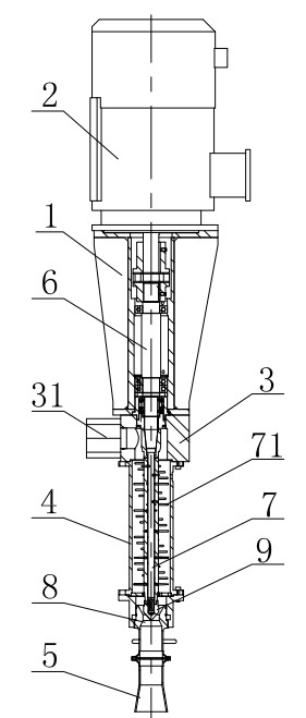
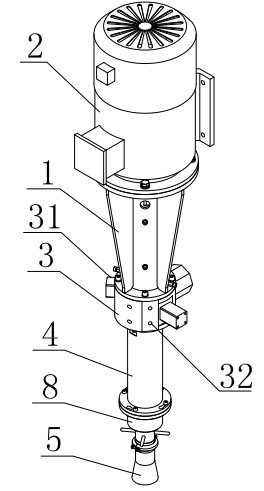
[0011] Such as figure 1 , figure 2 , image 3 As shown, the polyurethane mixing device has a structure comprising: a connecting seat 1, a motor 2 is installed on the connecting seat 1, a valve seat 3 is provided at the lower end of the connecting seat 1, and a mixing cylinder 4 is provided at the lower end of the valve seat 3, The lower end of the mixing barrel 4 is provided with a discharge port 5, the connecting seat 1 is provided with a connecting shaft 6, the upper end of the connecting shaft 6 is connected with the output shaft of the motor 2, and the lower end of the connecting shaft 6 After passing through the valve seat 3, it is connected to the top of the mixing rod 7 in the mixing barrel 4. The valve seat 3 is provided with a feed port 31, and the feed port 31 communicates with the inner cavity of the mixing barrel 4. ,...


PUM


Abstract

The invention discloses a polyurethane mixing device, The structure of the device comprises a connecting seat; the connecting seat is provided with a motor; the lower end of the connecting seat is provided with a valve seat; a mixing barrel is arranged at the lower end of the valve seat; a discharge hole is arranged at the lower end of the mixing barrel; the connecting seat is internally provided with a connecting shaft; the upper end of the connecting shaft is connected with an output shaft of the motor; the lower end of the connecting shaft passes through the valve seat and is connected with the top of a mixing bar arranged in the mixing barrel; the valve seat is provided with a feeding hole; the feeding hole is communicated with an inner cavity of the mixing barrel; the valve seat is also provided with a water inlet which is also communicated with the inner cavity of the mixing barrel; and a mixing needle is arranged along the double-helix line of the longitudinal direction on the outer wall of the mixing bar. The polyurethane mixing device has the advantages of convenience in cleaning, uniformity in mixing and lighter structure.

Description

technical field [0001] The invention relates to a polyurethane mixing device. Background technique [0002] Polyurethane foam is widely used, and its semi-rigid polyurethane products mainly include steering wheels and automobile dashboards. At present, the foaming method is generally used in the production of polyurethane foam, that is, the raw materials are mixed under high-speed stirring and then foamed. The structure of the traditional polyurethane mixing device includes: a connecting seat, a motor is installed on the connecting seat, a valve seat is arranged at the lower end of the connecting seat, a mixing barrel is arranged at the lower end of the valve seat, and a discharge valve is arranged at the lower end of the mixing barrel. A connecting shaft is arranged in the connecting seat, the upper end of the connecting shaft is connected with the output shaft of the motor, and the lower end of the connecting shaft passes through the valve seat and connects with the top o...

Claims


Application Information

Patent Timeline
Patent Type & Authority Applications(China)
IPC IPC(8): B29B7/12B29B7/26
Inventor 王汉力
Owner 王汉力
Features
  • R&D
  • Intellectual Property
  • Life Sciences
  • Materials
  • Tech Scout
  • Unparalleled Data Quality
  • Higher Quality Content
  • 60% Fewer Hallucinations
Learn More