Method of manufacturing a diffusely-reflecting polarizer having a substantially amorphous nano-composite continuous phase
What is AI technical title?
AI technical title is built by Patsnap AI team. It summarizes the technical point description of the patent document.
A polarizer, diffuse reflection technology, applied in the directions of diffusing elements, polarizing elements, instruments, etc., can solve problems such as poor adhesion, damage to the bond between matrix and dopant, and degradation of film optical properties
Inactive Publication Date: 2012-07-25
SKC HAAS DISPLAY FILMS CO LTD +1
View PDF6 Cites 1 Cited by
Summary
Abstract
Description
Claims
Application Information
AI Technical Summary
This helps you quickly interpret patents by identifying the three key elements:
Problems solved by technology
Method used
Benefits of technology
Problems solved by technology
But optical films made of polymers filled with inorganic dopants suffer from a series of problems
Typically poor adhesion between inorganic particles and polymer matrix
Consequently, the optical properties of the film degrade when stress or strain is applied to the matrix, both because the bond between the matrix and the dopant is compromised and because the rigid inorganic dopant may fragment
Additionally, inorganic dopant orientation requires processing steps and considerations that complicate production
Method used
Image
Click on the blue label to locate the original text in one second.
Reading with bidirectional positioning of images and text.
Examples
Embodiment Construction
[0018] definition:
[0019] The terms "specular reflectance", "specular reflection" or "specular reflectance" R s Refers to the reflectance of light entering the exit cone with a vertex angle of 16° centered around the mirror angle. The term "diffuse reflectance", "diffuse reflectance" or "diffuse reflectance" R d Represents the reflection of rays outside the specular cone defined above. The term "total reflectance", "total reflectance" or "total reflectance" R t Represents the total reflectance of all rays from a surface. Thus, the total reflection is the sum of the specular and diffuse reflections.
[0020] Similarly, the terms "specular transmittance" and "specular transmittance" T s In this paper, it represents the transmission of light rays into an exit cone with a vertex angle of 16° centered near the specular direction. The terms "diffuse transmittance" and "diffuse transmittance" T d In this context denotes the transmission of all rays outside the specular cone ...
PUM
Property
Measurement
Unit
thickness
aaaaa
aaaaa
refraction
aaaaa
aaaaa
transmittivity
aaaaa
aaaaa
Abstract
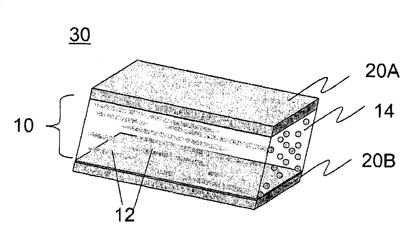
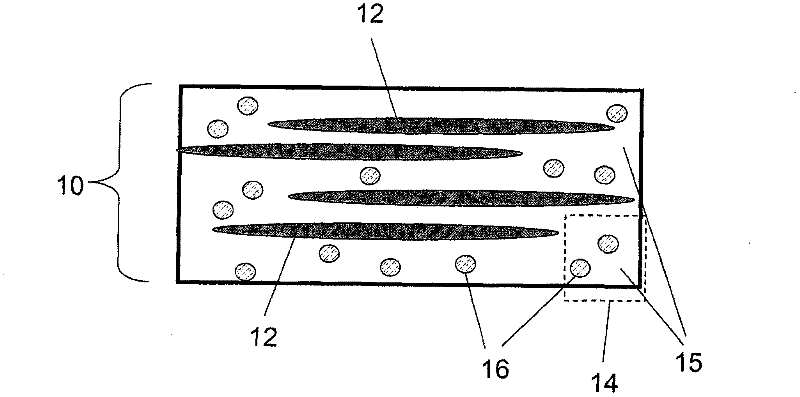
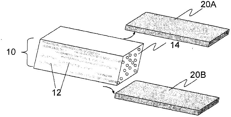
The present invention provides a method for manufacturing a diffusely reflecting polarizer, comprising the steps of: coextruding first and second polymers through a chaotic mixer and a sheeting die to produce a cast sheet with a desired blend morphology and stretching said cast sheet to produce a composite film containing a first polymer having a birefringence of less than 0.02, with said first polymer being a substantially amorphous nano-composite material, and a second polymer, the first polymer being a major phase, and the second polymer being a dispersed minor phase, wherein said first and second polymers taken together along a first axis for one polarization state of electromagnetic radiation exhibit a diffuse reflectivity R 1d , a specular reflectivity R 1s , a total reflectivity R 1t , a diffuse transmittance T 1d , a specular transmittance T 1s , and a total transmittance T 1t , and along a second axis for another polarization state of electromagnetic radiation exhibit a diffuse reflectivity R 2d , a specular reflectivity R 2s , a total reflectivity R 2t , a diffuse transmittance T 2d , a specular transmittance T 2s , and a total transmittance T 2t , the said first and second axes being orthogonal, wherein the parameters of composition, chaotic mixing, stretch temperature, stretch ratio for the process and Tg, and refractive index of the first and second polymers are selected to satisfy the equations: (1) R 1d is greater than R 1s ; and (2) T 2t / (1-0.5(R 1t +R 2t ))>1.35.
Description
technical field [0001] The present invention relates to a method of making a diffuse reflective polarizer comprising a film having a first polymer dispersed in the first polymer, the first polymer being substantially non- Crystalline nanocomposites are almost isotropic materials. technical background [0002] A reflective polarizing film transmits light of one polarization and reflects light of a polarization perpendicular to that polarization. They are used in LCDs to enhance light efficiency. A series of films have been disclosed to achieve the effect of reflective polarizing films, among them, diffuse reflective polarizers are the most attractive because their use eliminates the need for diffusers in LCDs, which reduces the LCD's performance. Complexity. U.S. Patent No. 5,783,120 teaches a diffusely reflective polarizing film comprising a film comprising an immiscible mixture having a first continuous phase (also referred to herein as the The proportion of the mixture...
Claims
Application Information
Patent Timeline
Application Date:The date an application was filed.
Publication Date:The date a patent or application was officially published.
First Publication Date:The earliest publication date of a patent with the same application number.
Issue Date:Publication date of the patent grant document.
PCT Entry Date:The Entry date of PCT National Phase.
Estimated Expiry Date:The statutory expiry date of a patent right according to the Patent Law, and it is the longest term of protection that the patent right can achieve without the termination of the patent right due to other reasons(Term extension factor has been taken into account ).
Invalid Date:Actual expiry date is based on effective date or publication date of legal transaction data of invalid patent.

