Electro-hydraulic point switch

A technology of switch machines and electric motors, applied in hydraulic equipment for manipulating turnouts or line breakers, electrical equipment for manipulating turnouts or line breakers, railway car body parts, etc., which can solve the high failure rate of oil pipelines , Oil pipeline leakage, failure to seal, etc.

Active Publication Date: 2012-07-25
TIANJIN HUIHUANG LUYANG TECH
View PDF7 Cites 11 Cited by
  • Summary
  • Abstract
  • Description
  • Claims
  • Application Information

AI Technical Summary

Problems solved by technology

[0006] (3) Tight sealing cannot be achieved. In the switch machine in the prior art, the two indicating rods included in the indicating mechanism are generally square in section, arranged side by side, extending out of the chassis, and the two indicating rods are fixed at one end, while the other One end is often separated, so it is difficult to seal between the two indicating rods and between them and the chassis; for the hydraulic station with separate structure, the hydraulic cylinder device is set in the chassis, and the oil tank and oil pump are set outside the chassis. The oil pipeline of the chassis also makes it more difficult to seal
[0007] (4) The existing point machine adopts the inspection column inserted into the notch of the indicating rod to indirectly check the position of the switch rail or the center rail, and the vertically moving inspection column has many intermediate links in the drive and transmission, the structure is complex, and the reliability is poor
[0008] (5) Existing sque...

Method used


Image

  • Electro-hydraulic point switch
  • Electro-hydraulic point switch
  • Electro-hydraulic point switch

Examples


Embodiment Construction

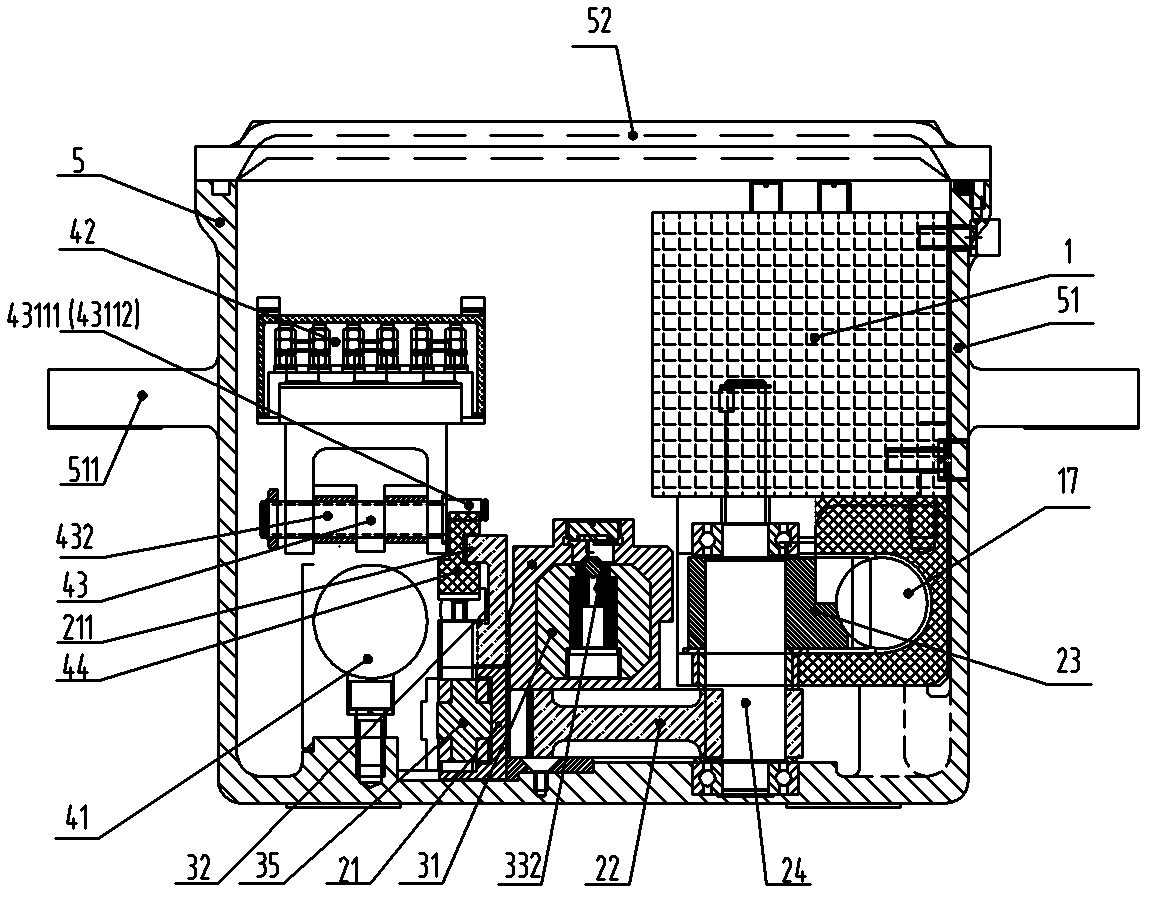
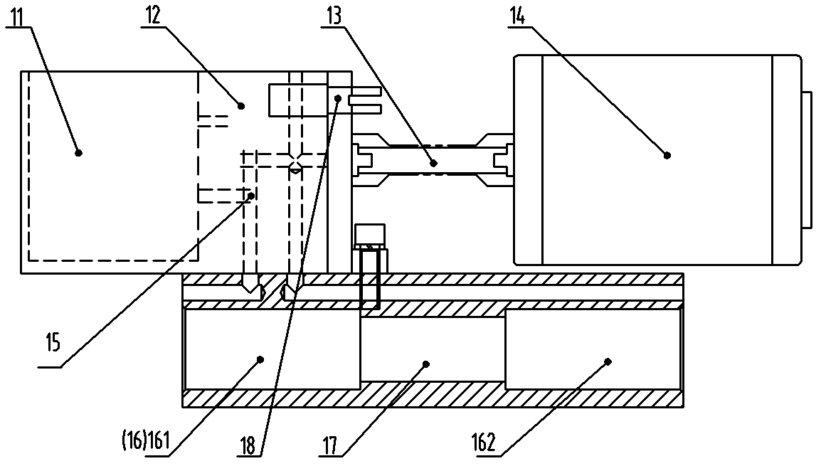
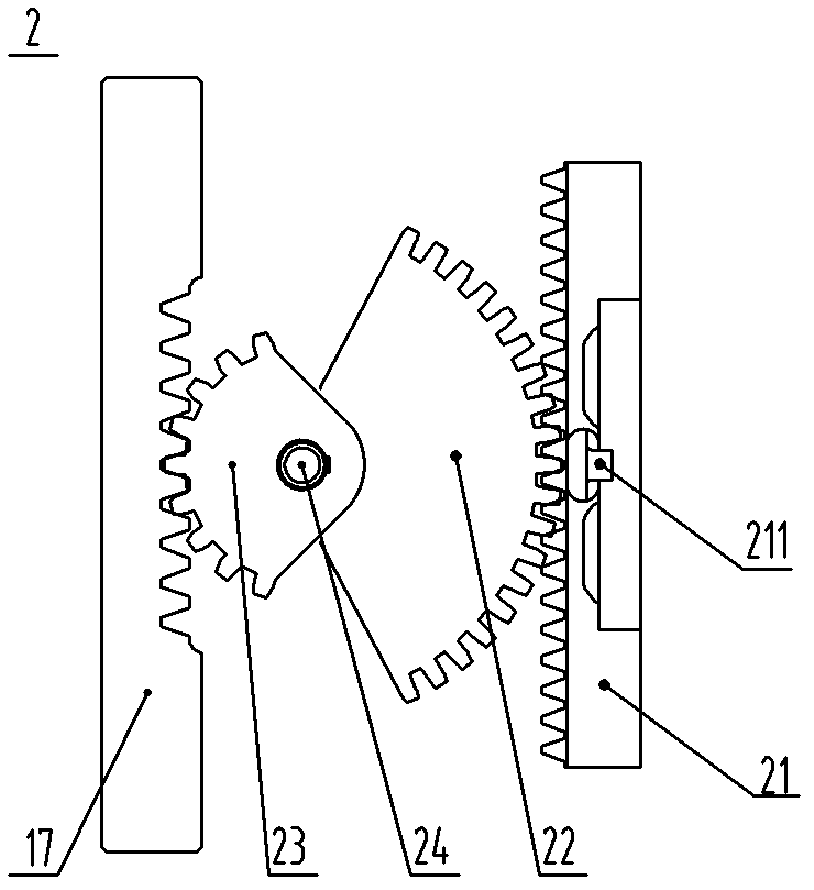
[0095] Such as figure 1 , figure 2 , image 3 and Figure 15 As shown, an electro-hydraulic switch machine provided by the present invention includes a motor 14, a hydraulic assembly 1, a transmission mechanism 2, a conversion locking mechanism 3 and an indication mechanism 4, which are connected to each other.

[0096] The oil cylinder 16 in the hydraulic assembly 1 is a double-acting oil cylinder; the cylinder body is fixed, and the piston moves; the two oil cylinders 161 and 162 are arranged concentrically. The three-phase AC motor 14 is connected to the oil pump through the motor oil pump transmission shaft 13 , and the oil pump is connected to the oil tank 11 and the oil cylinder 16 through the integrated oil pipeline 15 . The piston rod in the hydraulic assembly 1 is processed into a rack tooth shape to form a piston rack 17, and the piston rack 17 passes through the transmission mechanism 2 composed of a rack and pinion and the conversion locking mechanism and The ...


PUM


Abstract

The invention discloses an electro-hydraulic point switch, comprising a motor, a hydraulic assembly, a transmission mechanism, a switch-and-lock mechanism and an expressing mechanism, which are interconnected, wherein a cylinder in the hydraulic assembly is a double-acting cylinder; a cylinder body is fixed, in which a piston moves; a rack tooth shape is processed on a piston rod in the hydraulic assembly to form a piston rack; and the piston rack is connected with the switch-and-lock mechanism and the expressing mechanism by the transmission mechanism composed of gears and racks so as to enable an acting rod for driving a point rail in the switch-and-lock mechanism to move and lock, and enable the expressing mechanism to correspondingly act on to give out the placing or non-placing related expression. The point switch can accurately push a plurality of point switches with point rail conversion switches to act synchronously. The point switch can accurately convert locking and unlocking action parts, effectively shorten the actual movement distance of an expressing part so as to drastically reduce the appearance size of the whole machine and convert into a manual operation mode conveniently and safely, and has the advantages of simplicity and lightness in operation and good sealing performance of the whole machine.

Description

technical field [0001] The invention relates to a switch machine, in particular to an electrohydraulic switch machine. Background technique [0002] The electro-hydraulic switch machine is a special equipment for centralized control of switching switches in railways, underground railways, and urban rail transit stations. It can convert and lock the point rail or center rail of the switch, and at the same time give the position indication of the corresponding point rail. [0003] The electro-hydraulic switch machines in the prior art include electric motors, hydraulic stations, switching and locking mechanisms, and display mechanisms, which are connected to each other; all existing domestically produced switch machines can meet the requirements of the "General Technology for Switch Machines" promulgated by the Ministry of Railways. conditions" requirements, however, they also have some disadvantages: [0004] (1) The synchronous action of the point rail or the core rail of ...

Claims


Application Information

Patent Timeline
IPC IPC(8): B61L5/04B61L5/06
Inventor 吴学文何家林张建铭李纪勇宋明惠关雪飞马天宇
Owner TIANJIN HUIHUANG LUYANG TECH
Why Eureka
Try Eureka