Hydraulic rotary system and engineering vehicle

A rotary system, hydraulic technology, applied in the direction of fluid pressure actuating devices, servo motors, servo motor components, etc., can solve problems such as pressure fluctuations in the hydraulic system, eliminate pressure fluctuations, improve stability and comfort, and simple control schemes Effect

Active Publication Date: 2012-07-25
ZOOMLION HEAVY IND CO LTD
View PDF7 Cites 7 Cited by
  • Summary
  • Abstract
  • Description
  • Claims
  • Application Information

AI Technical Summary

Problems solved by technology

[0005] The invention provides a hydraulic rotary system, which is mainly used to solve the problem of pressure fluctuation of the hydraulic system caused by the interference of the load pressure during the rotary process of the hydraulic rotary system

Method used


Image

  • Hydraulic rotary system and engineering vehicle
  • Hydraulic rotary system and engineering vehicle
  • Hydraulic rotary system and engineering vehicle

Examples


Embodiment 1

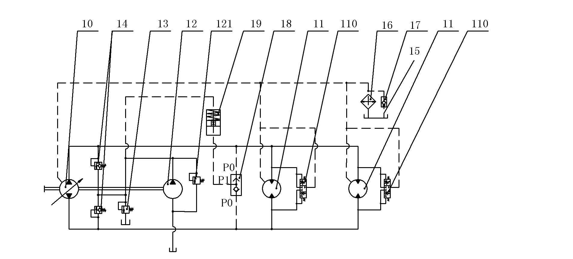
[0024] Please refer to figure 1 , which shows a hydraulic schematic diagram of an embodiment of the hydraulic swing system according to the present invention. The hydraulic slewing system includes: a slewing variable pump 10, a supplementary oil circuit connected in parallel to both ends of the slewing variable pump 10, a slewing motor 11 directly connected to the slewing variable pump 10, and a slewing buffer device. The number of slewing motors 11 is one or more. A flushing valve 110 is connected in parallel at both ends of the swing motor 11 , and the swing buffer device is connected in parallel at both ends of the swing motor 11 and communicated with the oil supply circuit for buffering pressure fluctuations in the hydraulic swing system. Wherein, the charging circuit includes a charging pump 12 and a charging pressure relief valve 13 , the charging pump 12 is coaxially driven with the rotary variable displacement pump 10 , and a charging safety overflow valve 121 is conne...

Embodiment 2

[0035] see Figure 4 , which shows a schematic diagram of the hydraulic principle of the second embodiment of the hydraulic swing system according to the present invention. The hydraulic slewing system includes: a slewing variable pump 20, an oil supply circuit connected in parallel at both ends of the slewing variable pump 20, a slewing motor 21 directly connected to the slewing variable pump 20, and a slewing buffer device. The number of slewing motors 21 is one or more. A flushing valve 210 is connected in parallel at both ends of the swing motor 21 , and the swing buffer device is connected in parallel at both ends of the swing motor 21 and communicated with the oil supply circuit for buffering pressure fluctuations in the hydraulic swing system. Wherein, the charging circuit includes a charging pump 22 and a charging pressure relief valve 23 , the charging pump 22 is coaxially driven with the rotary variable displacement pump 20 , and a charging safety overflow valve 221 ...


PUM


Abstract

The invention discloses a hydraulic rotary system comprising a rotary variable-capacity pump, an oil replenishing loop connected to both ends of the rotary variable-capacity pump in parallel, a rotary motor which is directly communicated with the rotary variable-capacity pump, and a rotary buffering device, wherein the rotary buffering device is connected to both ends of the rotary motor in parallel, is also communicated with the oil replenishing loop and is used for buffering pressure fluctuation in the hydraulic rotary system. By adding a control valve and a vibration damping valve according to the hydraulic rotary system, the pressure fluctuation generated in the rotary process of the rotary system can be effectively eliminated, and the stability and the comfort of the operation of the rotary system are enhanced. Meanwhile, pressure oil in the hydraulic rotary system disclosed by the invention flows out of the vibration damping valve after the pressure of the system is constructed by the pressure oil through a damping component on the vibration damping valve, and also flows into an oil outlet of an oil replenishing pump. In this way, the pressure oil also enters the oil replenishing loop of the system. The problem of needing to select an oil replenishing pump with larger output volume because the oil replenishing quantity of the system is insufficient is avoided.

Description

technical field [0001] The invention relates to the field of hydraulic systems, in particular to a hydraulic rotary system and an engineering vehicle equipped with the system. Background technique [0002] The slewing mechanism, as one of the important actuators for lifting heavy objects in construction cranes, is used to drive the upper part of the crane to make a slewing action. At present, the crane slewing mechanism control system generally uses a hydraulic slewing closed system composed of a slewing pump and a slewing motor. The slewing pump and the slewing motor are directly connected through pipelines without any control valve in between. The rotary system is provided with pressure oil by the rotary pump to drive the rotary motor to run, and the hydraulic oil is circulated in the rotary pump, the rotary motor and the connecting pipeline. Considering the heating of the oil and the leakage of the oil pump and motor, the system is equipped with a charge circuit composed...

Claims


Application Information

Patent Timeline
Patent Type & Authority Applications(China)
IPC IPC(8): B66C23/86F15B11/02F15B13/02
Inventor 詹纯新刘权杨翔尹飞刘宇新刘建华刘劲松李迎兵王博徐晓东
Owner ZOOMLION HEAVY IND CO LTD
Why Eureka
Try Eureka