Multifunctional integrated floating debris control floating-tank system for hydraulic engineering

A water conservancy project, multi-functional technology, applied in the field of flotation control, can solve the problems of loss of flotation function, unfavorable technology integration development, failure to improve water environment, etc. development effect

Inactive Publication Date: 2014-03-12
CHANGJIANG RIVER SCI RES INST CHANGJIANG WATER RESOURCES COMMISSION
View PDF4 Cites 0 Cited by
  • Summary
  • Abstract
  • Description
  • Claims
  • Application Information

AI Technical Summary

Problems solved by technology

Due to the limited range of direct suction and drift by the discharge of the drift hole, it has little effect on the drift of large-area floating objects. When the drift hole is submerged, it loses the drift function; the drift needs to consume a lot of water (for example, the water level of the Three Gorges is 145 ~ 155m alone. Drift flow of hole row is about 600~1000m 3 / s), it will reduce the power generation benefit of the project; drifting does not improve the water environment, and it is not good for downstream projects in rivers with cascade development
[0006] To sum up, the existing drift cleaning and control methods cannot solve the problem of floating objects well, are not conducive to technology integration and development, and are difficult to form a long-term drift cleaning mechanism

Method used


Image

  • Multifunctional integrated floating debris control floating-tank system for hydraulic engineering
  • Multifunctional integrated floating debris control floating-tank system for hydraulic engineering
  • Multifunctional integrated floating debris control floating-tank system for hydraulic engineering

Examples


Embodiment Construction

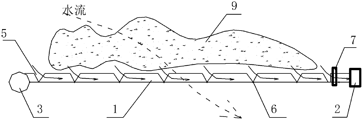
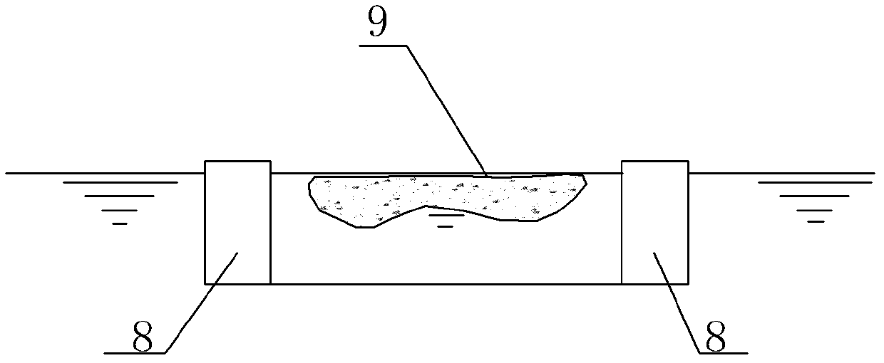
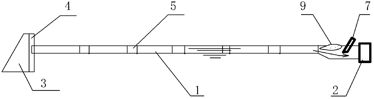
[0026] As shown in the picture- Figure 4 As shown, the multifunctional integrated floating tank system of the present invention mainly includes a floating tank 1, a positioning facility 3 and a floating cleaning machine 7, wherein: the floating tank 1 is composed of several single tanks hinged or flexibly connected by connecting hinges 6, There are cavities 8 on both sides of the tank body, a floating guide gate 5 is set along the floating side of the floating tank 1, one end of the floating tank 1 is connected to the positioning facility 3, and a chute is provided on the connecting side between the positioning facility 3 and the floating tank 1 4. Make the connection point of floating tank 1 move up and down with the change of water level. When the floating tank 1 is arranged in front of the power station, its outlet end is connected with the pivot drainage hole 2, and a cleaning and drifting machine 7 is set in the floating tank 1 close to the drainage hole 2. Generally, t...


PUM


Abstract

The invention relates to a multifunctional integrated floating debris control floating-tank system for hydraulic engineering, which is characterized in that a floating tank 1 is formed by hinging or flexibly connecting a plurality of single tanks, two sides of a body of the floating tank are provided with cavities, movable guide gates are longitudinally disposed on the side facing floating debris, and one end of the floating tank is connected with a positioning facility. When the floating tank is disposed in front of a power plant, an outlet end of the floating tank is connected with a pivot drainage hole. And a cleaning machine is disposed inside the floating tank and near the drainage hole. When the floating tank is disposed at a reservoir, the outlet end of the floating tank is connected with a pump station. The multifunctional integrated floating debris control floating-tank system for hydraulic engineering has the functions of floating debris blocking, guiding and cleaning, the pressure of cleaning the floating debris in front of a hydraulic engineering dam or in the reservoir can be relieved greatly, influence of the floating debris on power generation is relieved or eliminated effectively, surface environment, quality of water and the like in front of the dam can be improved, controllable cleaning of the floating debris can be achieved, the debris is controlled with no need of discharging, and integrated development of related technologies is promoted.

Description

technical field [0001] The invention relates to the treatment of floating objects in water conservancy projects, in particular to a multi-functional integrated control floating tank system for water conservancy projects. Background technique [0002] As we all know, there are floating objects in front of dams or reservoir areas of water conservancy projects. Large areas of floating objects pose a threat to the safe operation of the project and directly affect the power generation, shipping, ecological environment and water quality of the project. At present, the main methods of drift control include drift blocking and rowing, ship and manual drift cleaning, and hub drift removal, among which; [0003] Due to the drainage of the power station and the suspension of floating objects, the blocking method is easy to accumulate on the facing side of the floating block. Under the action of hydraulic, wind, wave and other factors, the floating objects in a large area will cross the ...

Claims


Application Information

Patent Timeline
Patent Type & Authority Patents(China)
IPC IPC(8): E02B15/10
Inventor 蔡莹黄国兵段文刚杨文俊史德亮王才欢邢领航姜治兵陈端王思莹杨金波李利
Owner CHANGJIANG RIVER SCI RES INST CHANGJIANG WATER RESOURCES COMMISSION
Why Eureka
Try Eureka