Detonation chamber of pulse detonation engine

A pulse detonation and engine technology, applied in mechanical equipment, intermittent injection devices, etc., can solve the problems of inability to effectively reduce back-propagation gas pressure, large loss of flow resistance in the detonation chamber, easy ablation, etc., and achieve improved use The effect of life, forward flow loss is small, and it is not easy to ablate

Inactive Publication Date: 2012-07-25
NORTHWESTERN POLYTECHNICAL UNIV
View PDF4 Cites 7 Cited by
  • Summary
  • Abstract
  • Description
  • Claims
  • Application Information

AI Technical Summary

Problems solved by technology

[0006] In order to avoid the deficiencies of the prior art, the present invention proposes a pulse detonation engine detonation chamber to improve the large flow resistance loss, easy ablation and air-breathing pulse detonation engine detonation of the detonation chamber in the prior art The problem that the chamber cannot effectively reduce the pressure of the reverse gas

Method used


Image

  • Detonation chamber of pulse detonation engine
  • Detonation chamber of pulse detonation engine
  • Detonation chamber of pulse detonation engine

Examples


Embodiment Construction

[0018] Now in conjunction with embodiment, accompanying drawing, the present invention will be further described:

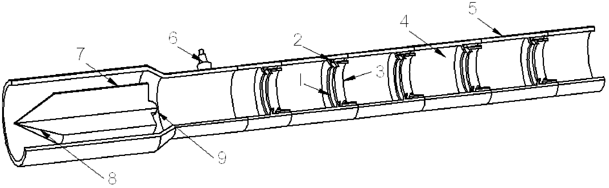
[0019] The field of application of the present invention is as figure 1 The detonation chamber of a pulse detonation engine is shown. However, the present invention is also applicable to certain burners that require detonation wave formation and reduced return gas pressure.

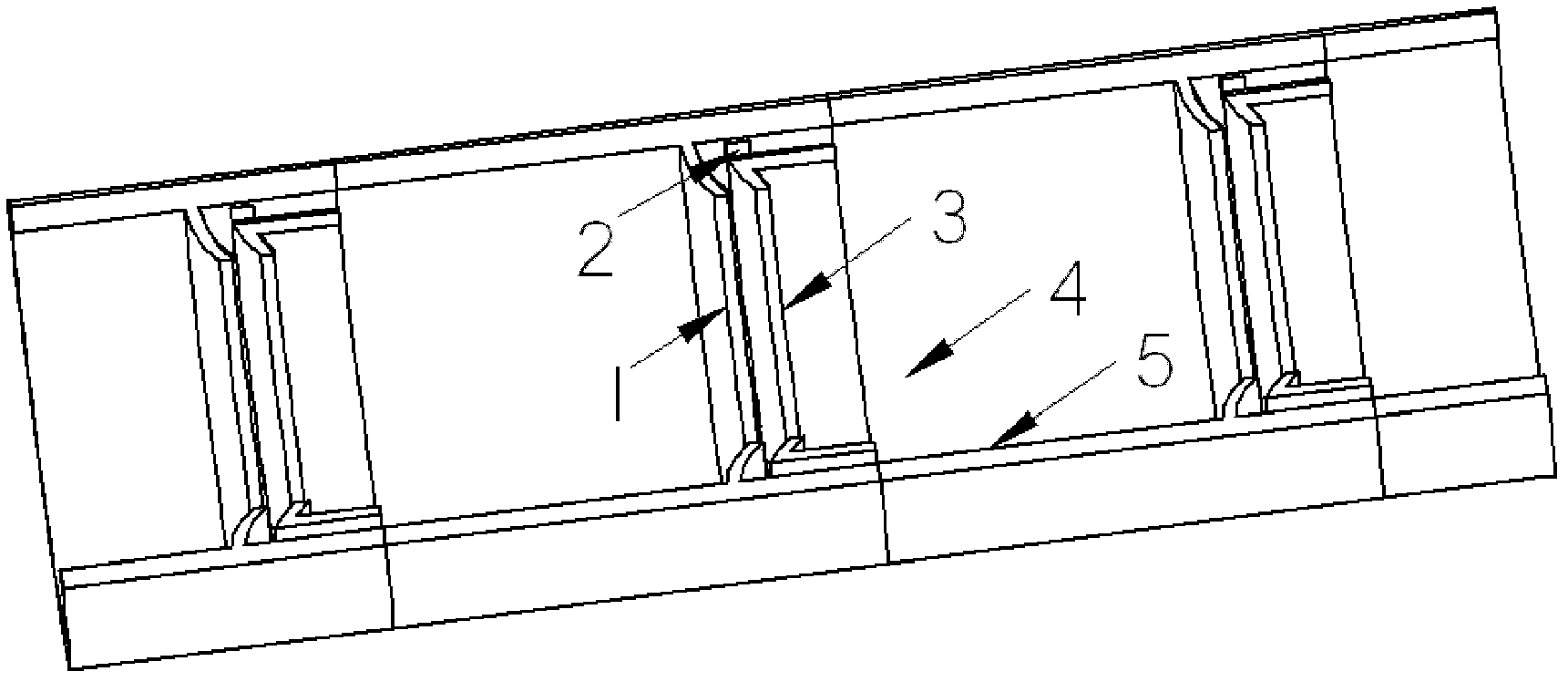
[0020] This example figure 2 Shown: 5 detonation enhancing devices are arranged on the inner wall of the pulse detonation engine, each detonation enhancing device is separated by 0.8 times the inner diameter of the inner wall of the engine; 3; along the air intake direction, a constriction section forming a gradually shrinking flow channel is provided, and then a drainage section is connected; the throat area of ​​the drainage section is the same as the throat area of ​​the constriction section, and the leading edge of the drainage section 3 shrinks along the The direction of the shrinka...


PUM


Abstract

The invention relates to a detonation chamber of a pulse detonation engine, which is characterized in that a plurality of detonation enhancing devices are arranged on the inner wall of an engine, and a distance between every two detonation enhancing devices is 0.5-1 time of the inner diameter of the inner wall of the engine. Each detonation enhancing device comprises a contraction section, a fixing rib and a flow guiding section. The contraction section forming a gradually contracted flow channel is arranged along the air inlet direction and then in linkage with the flow guiding section. Compared with a common Schelkin spirally-mutational flow channel, the forward direction flow losses are small, the forward direction flow losses in the detonation chamber is reduced, and the detonation waves can be formed in a short distance. The detonation enhancing devices are not easily ablated, and the service life of the detonation chamber can be effectively improved. Traditional Schelkin spirals are connected with the engine in a welding mode. When the engine works at high frequency, the temperature in the detonation chamber is high, and welding spots are easily ablated to enable the Schelkin spiral to be invalid.

Description

technical field [0001] The invention relates to the technical field of engines, in particular to a pulse detonation engine detonation chamber. Background technique [0002] The pulse detonation engine is a new concept propulsion device that uses high-temperature, high-pressure gas generated by intermittent detonation waves to generate thrust. Pulse detonation engines can be divided into rocket type and air-breathing type according to whether they have their own oxidant. [0003] There are two ways of detonation detonation, namely direct detonation and indirect detonation. The former requires a huge ignition energy, and the latter forms a detonation wave through the deflagration-to-detonation transition (DDT). Considering the practicality, the pulse detonation engine generally adopts the way of indirect detonation to obtain the detonation wave. Specifically, a small ignition energy is used to form a slow combustion wave, and then the detonation wave is finally formed throu...

Claims


Application Information

Patent Timeline
Patent Type & Authority Applications(China)
IPC IPC(8): F02K7/02
Inventor 王治武彭畅新郑龙席陈星谷卢杰胡明刘继华
Owner NORTHWESTERN POLYTECHNICAL UNIV
Why Eureka
Try Eureka