
Oil-in-water type heater oil tank

An oil-in-water heater technology, which is applied to machines/engines, fuel heat treatment devices, engine components, etc., can solve the problems of low heating efficiency and poor effect, and achieve high oil temperature, large heating area, and energy-saving effects. obvious effect

Active Publication Date: 2012-07-25
刘晶
View PDF5 Cites 7 Cited by
  • Summary
  • Abstract
  • Description
  • Claims
  • Application Information

AI Technical Summary

Problems solved by technology

[0011] In order to overcome the shortcomings of low heating efficiency and poor effect of existing heating oil tanks, the present invention proposes an oil-in-water heater tank

Method used


Image

  • Oil-in-water type heater oil tank
  • Oil-in-water type heater oil tank
  • Oil-in-water type heater oil tank

Examples


Embodiment Construction

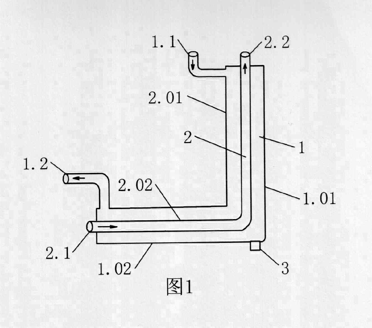
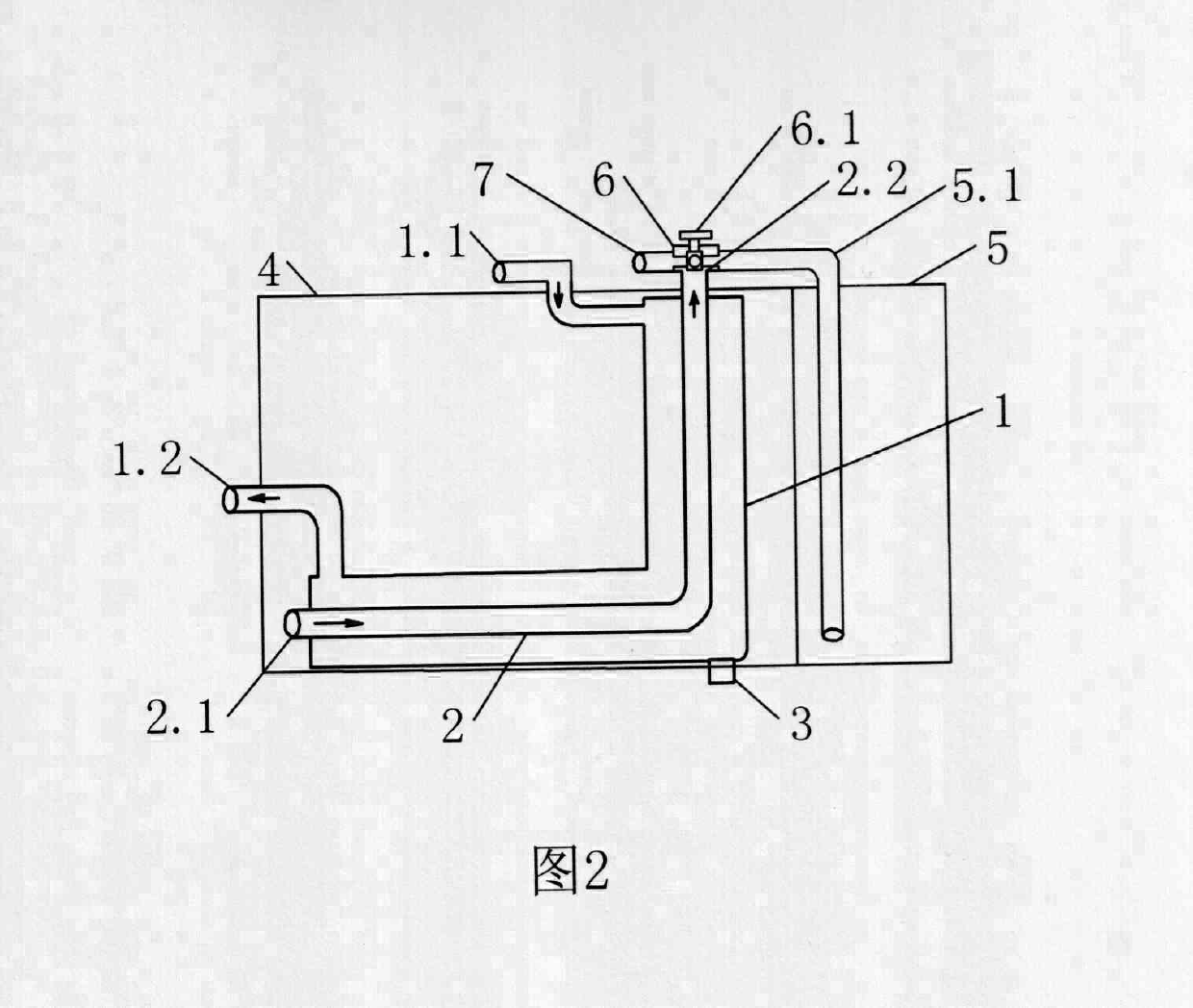
[0023] according to figure 1 with figure 2 As shown, the heater is composed of: the vertical section 1.01 of the water jacket and the horizontal section 1.02 of the water jacket are welded vertically to form the water jacket 1, and the water jacket inlet 1.1 is connected to the upper side of the vertical section of the water jacket. The end of the horizontal section of the pipe is connected to the water outlet 1.2 of the water casing, the horizontal section 2.02 of the oil suction pipe is placed in the horizontal section of the water casing, the vertical section 2.01 of the oil suction pipe is placed in the vertical section of the water casing, and the horizontal section of the oil suction pipe and the vertical section The connection between them is used as the oil suction pipe 2, and an outrigger 3 is provided at the bottom of one side of the horizontal section of the water casing.

[0024] The oil tank is composed of the main oil tank 4 and the auxiliary oil tank 5. The he...


PUM


Abstract

The invention provides an oil-in-water type heater oil tank. A heater formed by inserting an oil suction pipe into a water sleeve which is composed of a water sleeve transverse pipe and a water sleeve vertical pipe is arranged in a main oil tank, the oil suction pipe and a high number oil suction pipe are respectively communicated with a three-way oil valve; thereby forming the oil-in-water type heater oil tank. An auxiliary oil tank is arranged in the main oil tank of the heater oil tank; a water sleeve is arranged in the main oil tank; the oil suction pipe is arranged in the water sleeve, the high number oil suction pipe is arranged in the auxiliary oil tank, and then the oil suction pipe and the high number oil suction pipe are respectively communicated with an oil supply pipe after being communicated with the three-way oil valve. The oil-in-water type heater oil tank is characterized in that the water sleeve and the oil suction pipe are composed of vertical sections and transverse sections; the vertical sections are located at the bottom of the main oil tank, and the vertical sections are located at the middle part of the oil tank. The heater oil tank has the characteristics that the heater oil tank is large in heating area, high in oil temperature, great in energy-saving effect, and environment friendly. Therefore, the heater oil tank is appropriate for the oil tank at the low-temperature state of diesel engines and diesel vehicles.

Description

technical field [0001] The invention provides an oil-in-water heater tank in the field of internal combustion engines. Background technique [0002] Through patent retrieval, there is a kind of oil tank heater, the content of its manual abstract is: [0003] 1. A fuel tank heater, comprising: a heater body, an oil inlet pipe, an oil outlet pipe, a water inlet pipe, and a water outlet pipe. The heater body is cylindrical, and the heater body is sequentially provided with an inner water chamber, An oil chamber and an outer water chamber, the top of the inner water chamber communicates with the water inlet pipe, the bottom communicates with the outer water chamber, the inner water chamber is provided with a spiral oil pipe, and the oil outlet of the spiral oil pipe communicates with the oil outlet pipe, the said The oil inlet of the oil chamber is communicated with the oil inlet pipe, the oil outlet thereof is communicated with the oil inlet of the spiral oil pipe, and the top...

Claims


Application Information

Patent Timeline
IPC IPC(8): F02M37/00F02M31/14
Inventor 刘晶刘磊
Owner 刘晶
Learn More