

Pressure adjusting device and hydraulic system
A technology of pressure regulation and hydraulic system, which is applied in the direction of fluid pressure actuators, servo motor components, mechanical equipment, etc. It can solve the problems of unable to reduce interference pressure, etc., and solve the problem of difficult control of stability, prevent system pressure fluctuations, and simple structure Effect
- Summary
- Abstract
- Description
- Claims
- Application Information
AI Technical Summary
Problems solved by technology
Method used
Image

Examples
Embodiment 1
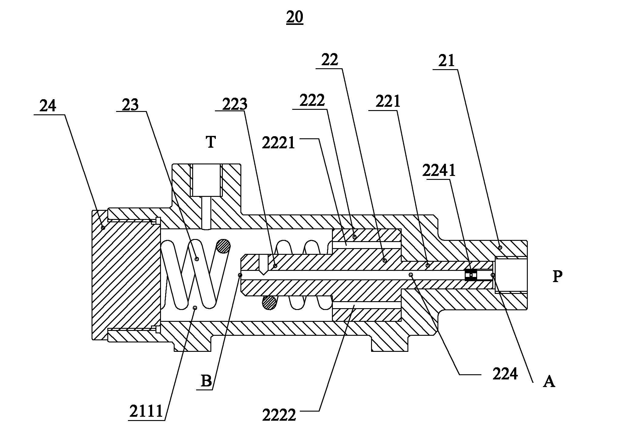
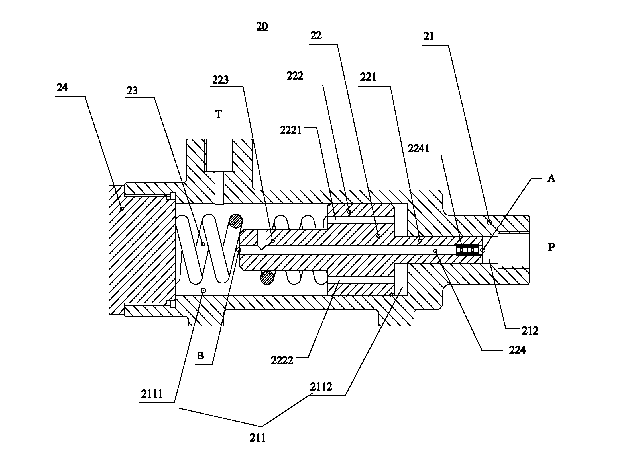
[0025] Please also refer to figure 2 and image 3 , which respectively show the structural schematic diagrams of an embodiment of the pressure regulating device 20 in the non-working state and in the working state according to the present invention. The pressure regulating device 20 includes: a valve body 21 , a first valve core 22 , and a first elastic member 23 .
[0026] The valve body 21 includes a first main chamber 211 and a pressure oil port P and an oil return port T in fluid communication with the first main chamber 211 . The first valve core 22 is disposed in the first main chamber 211 and divides the first main chamber 211 into a first elastic chamber 2111 and a first buffer chamber 2112 , and the first elastic chamber 2111 communicates with the oil return port T. The inside of the first valve core 22 is provided with a first flow channel 224 axially penetrating through it. Both ends of the first flow channel 224 are respectively connected to the pressure oil por...
Embodiment 2
[0038] see Figure 4 , which shows a schematic structural view of the second embodiment of the pressure regulating device according to the present invention.
[0039] In this embodiment, the pressure regulating device 30 includes a valve body 31 , a first valve core 32 , a first elastic member 33 , a first plug 34 , a second valve core 37 , a second elastic member 38 , and a second plug 39 .
[0040] The valve body 31 includes a first main cavity 311 , a second main cavity 316 , a pressure oil port P1 in fluid communication with the first main cavity 311 , and an oil return port T1 in fluid communication with the second main cavity.
[0041] The first valve core 32 is disposed in the first main chamber 311 and divides the first main chamber 311 into a first elastic chamber 3111 and a first buffer chamber 3112 , and the first elastic chamber 3111 communicates with the oil return port T1 . The inside of the first valve core 32 is provided with a first flow channel 324 axially ...
Embodiment 3
[0053] The embodiment of the present invention also provides a hydraulic system, which adopts the above-mentioned pressure regulating device, and the pressure regulating device is connected in the hydraulic system through a pressure oil port, an oil return port and an oil drain port, wherein the pressure oil port is usually connected in parallel Load-sensing working pressure port for hydraulic systems. The pressure regulating device can be configured with different first damping elements and second damping elements.
[0054] Since the pressure regulating device is provided with a flow channel inside the valve core, or a flow channel with a damping member installed inside the valve core and an elastic member, the fluctuation of the load pressure will be affected by the elastic member, the flow channel or the flow channel. And the cushioning effect of damping parts, so it can greatly reduce the interference pressure caused by external interference, prevent system pressure fluctu...
PUM
 Abstract
Description
Claims
Application Information