
Transmission device for improving transmission efficiency of intermediate shaft type gear box

A technology of gearbox transmission and transmission, applied in transmission, gear transmission, transmission control and other directions, can solve the problems of oil churning loss, wind resistance loss, oil churning loss and wind resistance loss unavoidable, etc. Life, improve temperature rise, improve the effect of overall transmission efficiency

Inactive Publication Date: 2012-07-25
TONGJI UNIV
View PDF3 Cites 3 Cited by
  • Summary
  • Abstract
  • Description
  • Claims
  • Application Information

AI Technical Summary

Problems solved by technology

[0004] In traditional transmissions, most of the gears are in the state of constant meshing rotation. Usually, when working in a certain gear, the gear corresponding to the transmission gear rotates under load, and the transmission gear pairs corresponding to other gears rotate without load. Although the transmission gear pairs in other gears No load, but oil churning loss and wind resistance loss caused by gear idling are inevitable
This is mainly because the transmission gear pair corresponding to the gear position of the traditional gearbox generally has an empty gear and the other gear is fixedly connected to the shaft. When the shaft is rotating, other gear pairs that do not participate in the gear work will rotate without load, and the rotation will naturally bring a certain amount of oil churning loss and windage loss

Method used


Image

  • Transmission device for improving transmission efficiency of intermediate shaft type gear box
  • Transmission device for improving transmission efficiency of intermediate shaft type gear box
  • Transmission device for improving transmission efficiency of intermediate shaft type gear box

Examples


Embodiment Construction

[0028] Please refer to the accompanying drawings and take the five-speed countershaft gearbox as an example to further describe the present invention.

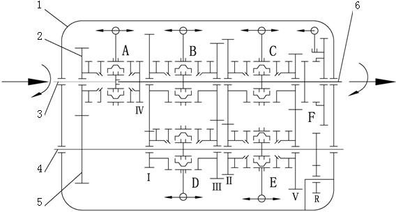
[0029] Such as figure 1 As shown, the present invention provides a transmission device for improving the transmission efficiency of an intermediate shaft type gearbox, including a gearbox case 1, an input shaft 3, an intermediate shaft 4, an output shaft 6, a first-stage transmission driving gear 2, a first Stage drive driven gear 5, direct gear engaging ring gear IV, corresponding transmission gears for each gear except direct gear and reverse gear (I, II, III, V), reverse gear R, synchronizers A-E and bearings, Except for the direct gear, other gears are all two-stage gear transmission, and share the first-stage transmission gears 2 and 5. The front end of the gearbox input shaft 03 is supported on the gearbox case 1 through a bearing, and the end is connected to the splined hub of the synchronizer A through a spline. The ...


PUM


Abstract

The invention discloses a transmission device for improving transmission efficiency of an intermediate shaft type gear box, wherein the front end of an input shaft of the gear box is supported on a gear box body by a bearing, the tail end of the input shaft of the gear box is connected with a splined hub of a synchronizer by a spline, a first-level transmission driving gear is sleeved on the input shaft, and a first-level transmission driven gear is fixedly connected on an intermediate shaft; the front end of an output shaft of the gear box is supported in a tail end hole of the input shaft and is fixedly connected with a direct-gear jointed gear ring, and the other end of the output shaft of the gear box is supported on the gear box body; the two ends of the intermediate shaft of the gear box are supported on the gear box body by a bearing; except direct gear shifting and gear reversing, all gears of the gear box are sleeved on the shaft by corresponding to the transmission wheels, and due to the adoption of the synchronizer for gear shifting, when a certain gear works, other gears do not rotate and keep in a static state. The transmission device has the advantages that the overall transmission efficiency of the gear box is effectively increased, the temperature rise of the gear box is improved, and the service life of the gear box is prolonged.

Description

technical field [0001] The invention relates to the field of automobile chassis and transmission, in particular to a transmission device for improving the transmission efficiency of an intermediate shaft gearbox. Background technique [0002] Due to the increasingly serious energy crisis and environmental pollution, energy efficiency has become the focus of attention. In the automotive industry, the transmission efficiency of a vehicle directly affects the fuel economy and emissions of the vehicle, and the transmission efficiency of the gearbox is a key factor in the transmission efficiency of the vehicle. [0003] Domestic and foreign research literature shows that gearbox power consumption can be divided into load power consumption and no-load power consumption. Among them, load power consumption mainly includes gear meshing power consumption and bearing power consumption under load conditions, and no-load power consumption It mainly includes the oil churning loss of the ...

Claims


Application Information

Patent Timeline
Patent Type & Authority Applications(China)
IPC IPC(8): F16H57/023F16H57/021F16H57/04F16H3/12F16H59/18
CPCF16H3/0915
Inventor 陈辛波卢志坚唐峰
Owner TONGJI UNIV
Learn More