Hydraulic self-driven double-gate disc gas gate valve

A double gate, hydraulic technology, applied in the direction of sliding valves, valve devices, engine components, etc., can solve the problem that the speed limit of the valve opening and closing speed electric device can not be increased quickly, the double-plate gas gate valve is large in size and takes up a lot of space, etc. problems, to achieve the effect of novel appearance structure, light weight, and lower height of the whole machine

Active Publication Date: 2015-01-07
YANGQUAN VALVE CO LTD
View PDF8 Cites 0 Cited by
  • Summary
  • Abstract
  • Description
  • Claims
  • Application Information

AI Technical Summary

Problems solved by technology

[0003] The purpose of the present invention is to solve the problem that the double-plate gas gate valve is large in size and heavy in weight, takes up a lot of space at the installation site, and the opening and closing speed of the valve is limited by the thread lead of the valve stem and the speed of the electric device and cannot be increased quickly.

Method used


Image

  • Hydraulic self-driven double-gate disc gas gate valve
  • Hydraulic self-driven double-gate disc gas gate valve

Examples


Embodiment 1

[0016] Implementation 1. Realization of the opening and closing mechanism

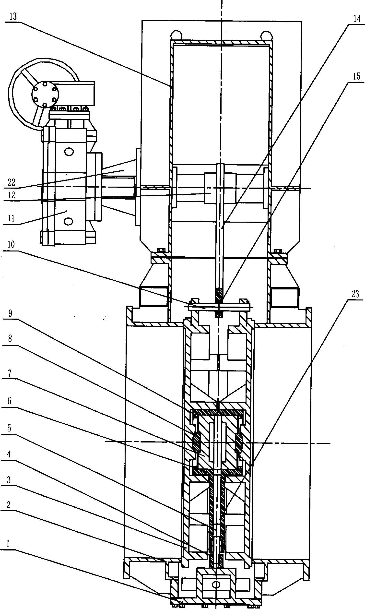
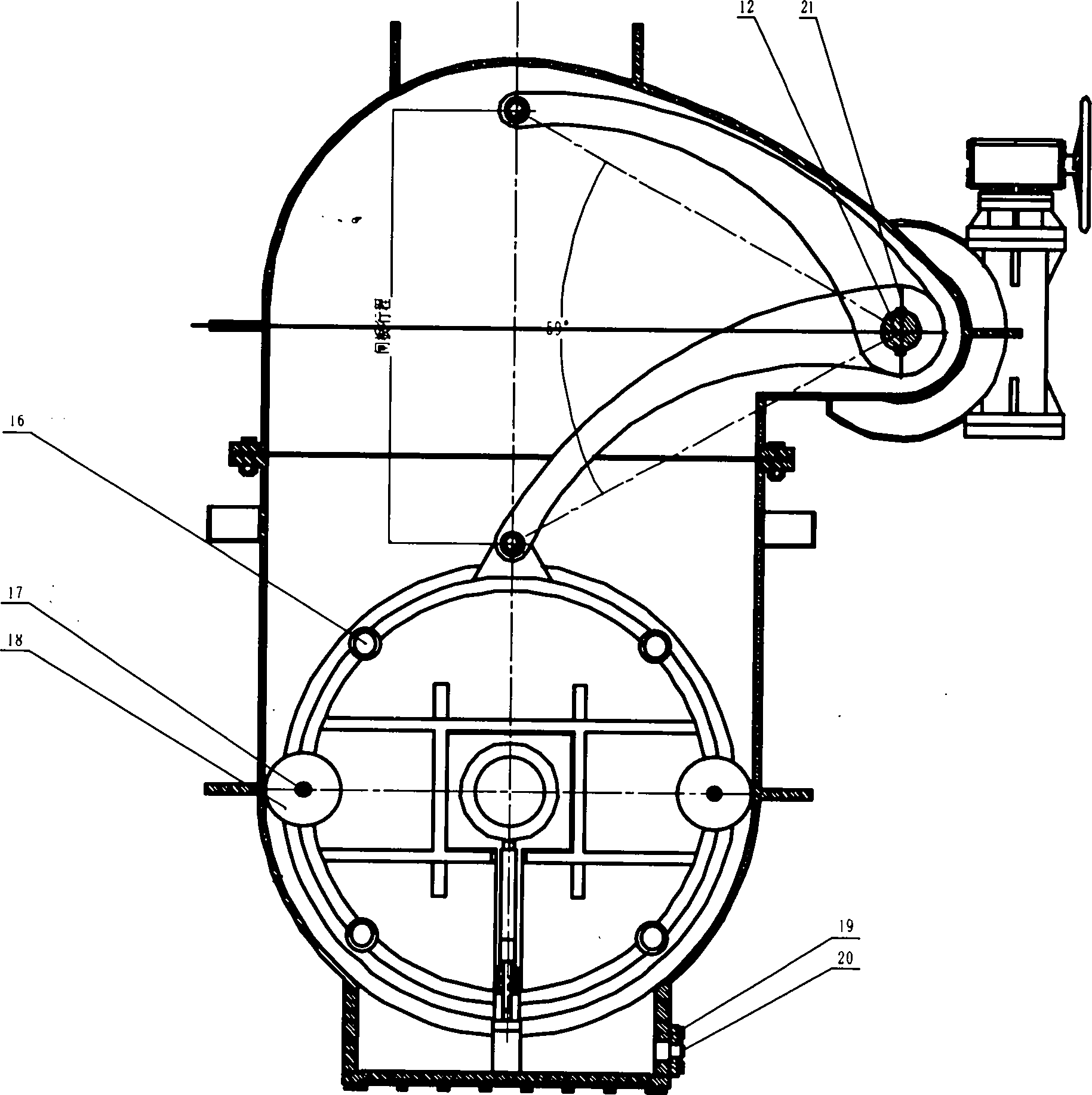
[0017] In the figure, the valve stem 12 is connected with the driving device 11, and the valve stem 12 and the rocker arm 14 are all connected by keys. The rocker arm 14 is connected with the gate plate 3 through the connecting shaft 10 . The gate 3 realizes the vertical movement of the gate 3 in the valve body 2 through the roller shaft 17 and the roller 18 . The valve rod 12 is driven by the driving device 11 to rotate at a fixed axis, so that the rocker arm 14 rotates, and drives the connecting shaft 10 and the gate plate 3 to move vertically. The roller 18 installed on the gate 3 rolls on the inner steel plate of the valve body 2, so that the gate moves in the vertical direction and partially rotates during the opening and closing process. This movement can make the sealing surfaces of the body and the plate get mutual Grinding to ensure that the dirt on the sealing surface is removed. In the ac...

Embodiment 2

[0018] Implementation 2. Realization of brake tightening mechanism

[0019] After the valve is closed in place, the adjustment pad 4 is pressed on the base 1 under the action of the gravity of the gate plate 3, so that the small piston 5 generates pressure on the hydraulic oil in the cylinder 6, and then the hydraulic oil generates pressure. According to the internal pressure of the liquid is equal everywhere In principle, the hydraulic oil in the oil cylinder 6 generates an outward thrust on the large piston 7, and the thrust is transmitted to the gate 3 through the top center 8, and then a sealing force is generated between the gate sealing surface and the valve body sealing surface to realize the protection against the medium. seal.

[0020] When the valve is opened, the rocker arm 14 swings upward under the drive of the driving device 11, so that the adjustment pad 4 is out of contact with the base 1, and at the same time, under the action of the small spring 23 in the oil...


PUM


Abstract

The invention relates to a hydraulic self-driven double-gate disc gas gate valve which solves the problems of large sealing force in sealing of the gas gate valve and large size of a driving device. The hydraulic self-driven double-gate disc gas gate valve is characterized in that a worm gear and a rocker arm are adopted to drive, wherein the rocker arm only needs to be rotated in a range of less than 60 DEG to complete the open and the close of a valve; the gate valve consists of an open-close mechanism, a locking mechanism, a valve body 2, a drive support 22 and a valve cover 13; wherein key connection is adopted between a valve rod 12 and a driving device 11 as well as between the valve rod 12 and the rocker arm 14; the rocker arm 14 and a gate disc 3 are connected through a connecting shaft 10; and the vertical movement of the gate disc 3 in the valve body 2 is realized through a roller shaft 17 and a roller 18. The gate valve has the advantages of small volume, light weight, convenience in installation and rapidness in open-close speed of the valve and is suitable for serving as an open-close device on pipelines containing tar and pure gas.

Description

technical field [0001] The invention belongs to the technical field of gate valve manufacture, and in particular relates to a hydraulic self-powered gas gate valve with double gates. It is suitable for use as an opening and closing device on pipelines containing tar gas and pure gas, and can also replace ordinary double-ram gas gate valves on pipelines that require full passage. This series of gate valves are widely used in metallurgy, coking and other industries. Background technique [0002] The sealing property of the existing ordinary double-plate gas gate valve is forced sealing, which requires a large sealing force and a large specification of the driving device. However, the gate tightening force of the hydraulic self-driven double-plate gas gate valve is provided by the self-weight of the gate plate, so the valve drive device It is only necessary to lift the gate, and it is not necessary to provide gate tightening force like ordinary double-plate gate valves, which ...

Claims


Application Information

Patent Timeline
Patent Type & Authority Patents(China)
IPC IPC(8): F16K3/16
Inventor 靳利铭梁志宝
Owner YANGQUAN VALVE CO LTD
Why Eureka
Try Eureka