Tool and method for measuring angular difference of tool face of oil field drilling instrument

A technology for tool face angle and oil field drilling, which is applied in angle/taper measurement and other directions, can solve the problems of difficult to identify whether the measurement tool projection is on a straight line, poor measurement accuracy, etc., and achieve the effect of convenient binding and convenient operation

Active Publication Date: 2012-07-25
CHINA NAT OFFSHORE OIL CORP +1
View PDF6 Cites 9 Cited by
  • Summary
  • Abstract
  • Description
  • Claims
  • Application Information

AI Technical Summary

Problems solved by technology

After the combined measurement tools used in the prior art are projected on the plane mirror, it is difficult to identify whether the projections of each measurement tool are on a straight line, so the measurement accuracy is poor

Method used


Image

  • Tool and method for measuring angular difference of tool face of oil field drilling instrument
  • Tool and method for measuring angular difference of tool face of oil field drilling instrument
  • Tool and method for measuring angular difference of tool face of oil field drilling instrument

Examples


Embodiment Construction

[0014] The present invention will be described in detail below in conjunction with the accompanying drawings and embodiments.

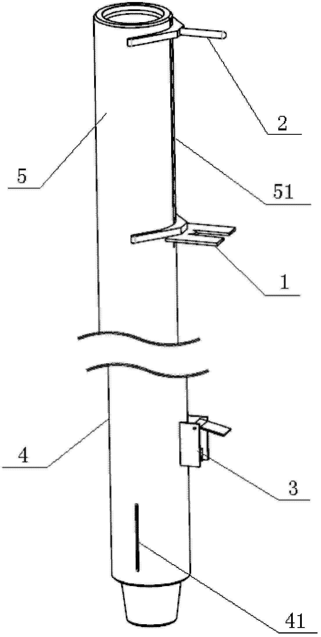
[0015] Such as figure 1 As shown, the present invention includes a plate-shaped aiming tool 1 , a tubular aiming tool 2 and a scope 3 . Through the combined action of the plate-shaped aiming tool 1 , the tubular aiming tool 2 and the scope 3 , the screw bending point of the screw 4 is measured, that is, the angle difference between the high-side tool surface marking line 41 and the drill collar marking line 51 of the drill collar 5 .

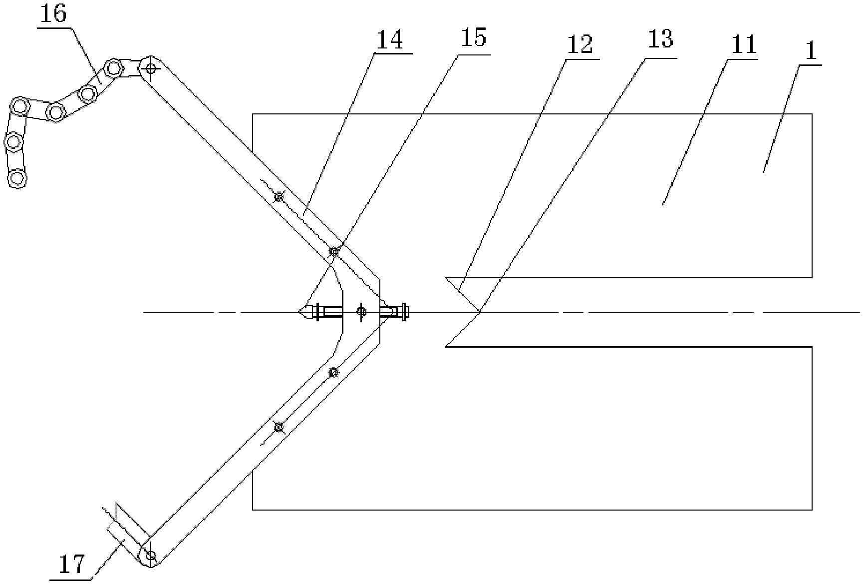
[0016] Such as figure 2 As shown, the plate-shaped aiming tool 1 of the present invention comprises a scale plate 11, and offers an " M " shape opening groove 12 inwardly along the middle part of one side of scale plate 11 , therefore, in " M " shape opening groove 12 On the center line of symmetry of , there is naturally a point 13 (ie the apex in the middle of the "M" letter). Corresponding to the "M"-shaped openi...


PUM


Abstract

The invention relates to a tool and a method for measuring an angular difference of a tool face of an oil field drilling instrument. The tool is characterized by comprising a platy aiming tool, a tubular aiming tool and a sighting telescope, wherein the platy aiming tool comprises a scale panel; an M-shaped open slot is formed inward along the middle part of one side of the scale panel; a V-shaped scale is arranged at the other side of the scale panel; a positioning rod is arranged at the symmetry center of the top of the V-shaped scale of the platy aiming tool; one end of the V-shaped scale of the platy aiming tool is provided with a hinge and the other side of the V-shaped scale is provided with calipers; the tubular aiming tool comprises a tubular scale; one end of the tubular scale is provided with a V-shaped scale; a positioning rod is fixed at the symmetry center of the top of the V-shaped scale of the tubular aiming tool; one end of the V-shaped scale of the tubular aiming tool is provided with a hinge and the other side of the V-shaped scale is provided with calipers; the sighting telescope comprises a telescope frame; the telescope frame comprises two lateral plates and a middle cross board; a rotating shaft is arranged on the two lateral plates and in front of the middle cross board; the rotating shaft is rotationally connected with a mirror plane; and a V-shaped notch is arranged upward at the middle position of the bottom of the cross board of the telescope frame.

Description

technical field [0001] The invention relates to an oilfield drilling instrument, in particular to an oilfield drilling instrument tool face angle difference measuring tool and a measuring method thereof. Background technique [0002] In the drilling measurement system, in order to drill the well according to the predetermined well deviation and azimuth, it is necessary to know the tool face angle difference of the oilfield drilling equipment. The drilling screw has a bending point, that is, the high side tool face, which has an angle with the drill collar marking line; there is also a certain angle between the drill collar marking line and the probe tool face, and the height can be calculated from these two angles. The angular difference between the edge tool face and the probe tool face. When measuring the angle between the screw and the drill collar marking line, it is necessary to use a set of measuring tools in combination to project the drill collar marking line and th...

Claims


Application Information

Patent Timeline
Patent Type & Authority Applications(China)
IPC IPC(8): G01B5/24
Inventor 陈红新石岩峰蒋世全王清松李峰飞石峻峰常永旺王聪
Owner CHINA NAT OFFSHORE OIL CORP
Why Eureka
Try Eureka