Iridium complexes for electrocatalysis

a technology of electrocatalysis and complexes, applied in the field of iridium complexes, can solve the problems of high sustained current concomitan

Active Publication Date: 2015-01-22
YALE UNIV
View PDF0 Cites 17 Cited by
  • Summary
  • Abstract
  • Description
  • Claims
  • Application Information

AI Technical Summary

Problems solved by technology

NHE results in high sustained current concomitant with oxygen production as measured by Clark electrode.

Method used


Image

  • Iridium complexes for electrocatalysis
  • Iridium complexes for electrocatalysis
  • Iridium complexes for electrocatalysis

Examples


example 1

Oxidative Transformation of Pre-Catalyst [Cp*Ir(bipy)OH]BF4 (1)

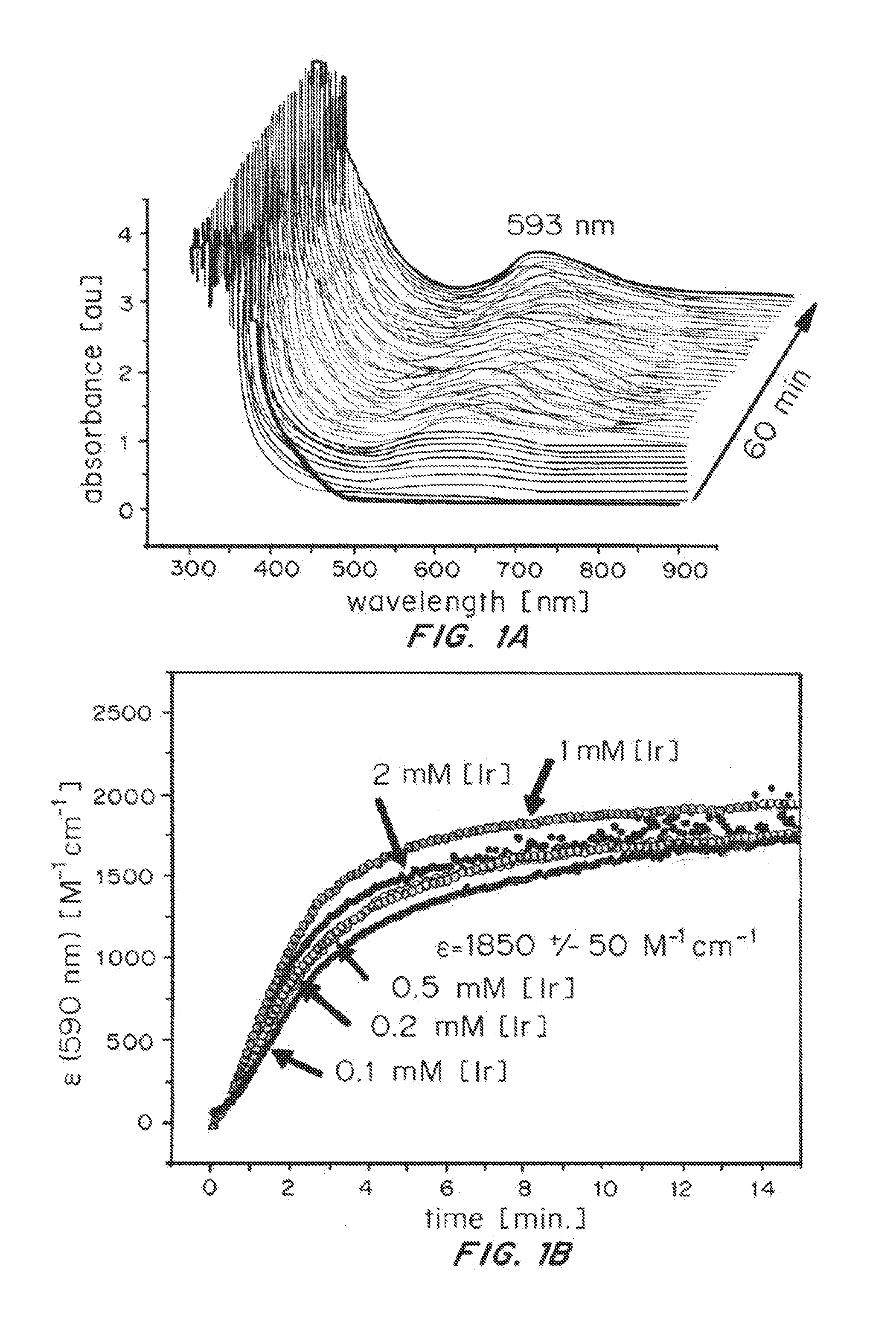
[0112][Cp*Ir(bipy)OH]BF4 (1) was reacted with NaIO4 in H2O (scheme 1).

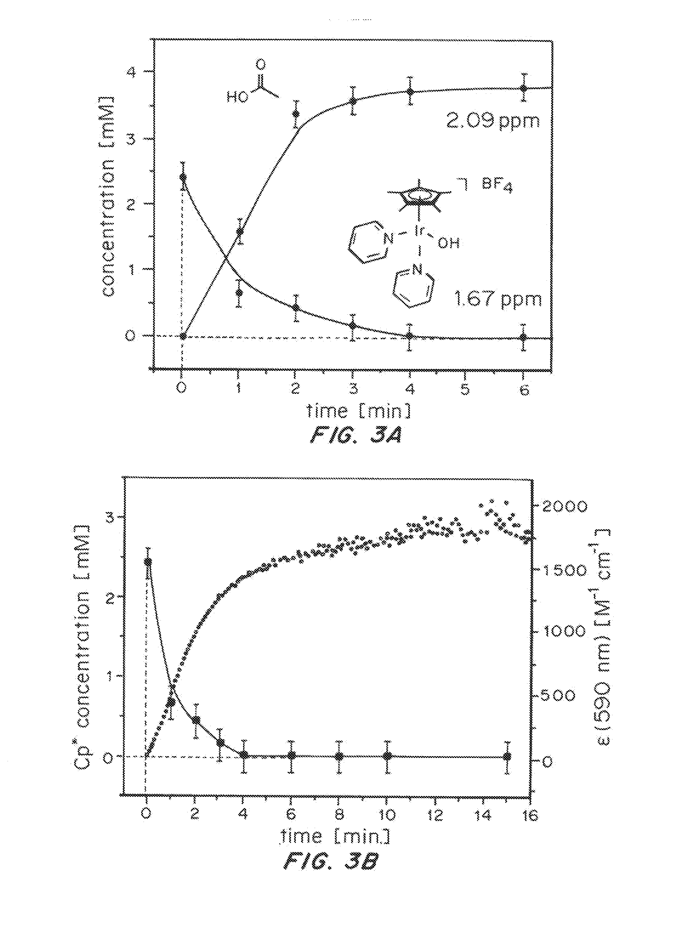
[0113]The reaction was monitored by UV-Vis spectroscopy. As shown in FIG. 1, a smooth evolution of the characteristic λmax ˜590 nm over the course of several minutes (FIG. 1A) was observed, making the reaction well suited for kinetic studies (FIG. 1B).

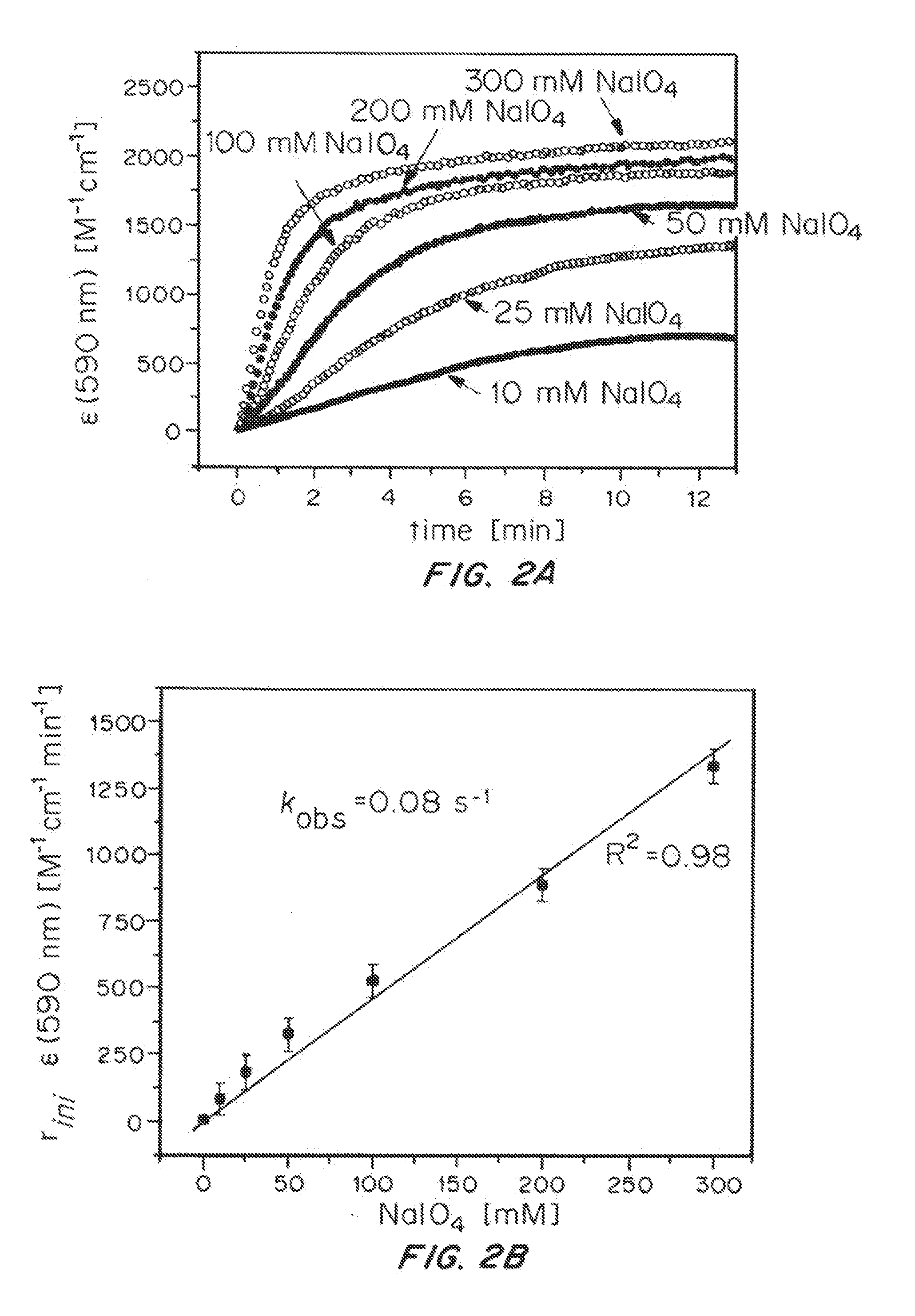
[0114]Variation of iridium concentration showed the rate of the reaction to be independent of [Ir] over more than one order of magnitude (FIG. 2), whereas variation of NaIO4 concentration showed a first-order rate dependence on oxidant (FIG. 2). Thus, the rate-determining step of the formation of the blue species appears to be the initial oxidation of the Cp* precursor, which proceeds with an apparent first-order rate constant kobs=0.08 s-1 corresponding to a half-life time of about 9 seconds for 1 under these conditions. Furthermore, the electronic transition at ˜590 nm likely involves a single metal cen...

example 2

Mechanism of Cp* Removal and Formation of Active Catalytic Species

[0116]In order to test how the Cp* ligand is oxidatively removed from the IrIII precursor, the coordinatively saturated sandwich complex [Cp*Ir(tacn)]SO4 (2, tacn=1,3,5-triazacyclononane) was prepared and treated with excess NaIO4 in H2O (Scheme 2).

[0117]In this case, the 1H-NMR and UV-Vis spectra of the complex remained entirely unchanged, and no O2 evolution was detectable by Clark-type electrode. The complete inertness of 2 towards oxidation demonstrates that neither direct oxidant attack on the coordinated Cp* ligand or outer-sphere electron transfer from the IrIII to the oxidant appears to occur, and oxidative transformation of Cp*IrIII complexes thus occurs within the coordination sphere of the metal, requiring at least one open site to proceed.

[0118]While [Cp*Ir(bipy)X]+ complexes with various hydrolysable X ligands in the open site readily react with aqueous periodate, no reaction occurred between [Cp*Ir(bipy)...

example 3

Oxygen Yield of IrIV Homogeneous Catalyst

[0136]Oxygen was detected with a Clark electrode using a custom made zero-headspace 10 mL glass cell, water jacketed for constant temperature. A Teflon cap through which the Clark electrode membrane contacted deionized water (adjusted to pH 2.5 using nitric acid) also held a catalyst-coated nanoITO film on FTO-coated glass sample that was submerged in the cell. Catalyst-loaded samples were prepared similarly to those used for electrochemistry, except with a 1.6 cm2 geometric surface area. The Clark electrode was allowed to stabilize while stirring the deionized water solution for one hour prior to injection with an oxidizing solution of freshly prepared NaIO4 in deionized water. Catalyst response and O2 generation occurred immediately, without any lag phase.

[0137]A typical experiment, used 25 μL of 0.25 M NaIO4 in deionized water. The oxygen content in the cell was monitored until oxygen evolution ceased, which for a loading of around 50 nmol...


PUM

PropertyMeasurementUnit
pHaaaaaaaaaa
Faradaic efficiencyaaaaaaaaaa

Abstract

Solution-phase (e.g., homogeneous) or surface-immobilized (e.g., heterogeneous) electrode-driven oxidation catalysts based on iridium coordination compounds which self-assemble upon chemical or electrochemical oxidation of suitable precursors and methods of making and using thereof are. Iridium species such as {[Ir(LX)x(H2O)y(μ-O)]zm+}n wherein x, y, m are integers from 0-4, z and n from 1-4 and LX is an oxidation-resistant chelate ligand or ligands, such as such as 2(2-pyridyl)-2-propanolate, form upon oxidation of various molecular iridium complexes, for instance [Cp*Ir(LX)OH] or [(cod)Ir(LX)] (Cp*=pentamethylcyclopentadienyl, cod=cis-cis,1,5-cyclooctadiene) when exposed to oxidative conditions, such as sodium periodate (NaIO4) in aqueous solution at ambient conditions.

Description

CROSS-REFERENCE TO RELATED APPLICATIONS[0001]This application claims the benefit of and priority to U.S. Ser. No. 61 / 840,201 filed Jun. 27, 2013 and which is incorporated by reference in its entirety.STATEMENT REGARDING FEDERALLY SPONSORED RESEARCH OR DEVELOPMENT[0002]This invention was made with government support under 1119826 and 1122492 awarded by National Science Foundation and under DE-FG02-07ER15909 awarded by Department of Energy and under GM008283 awarded by National Institutes of Health. The government has certain rights in the invention.FIELD OF THE INVENTION[0003]This invention is in the field of iridium complexes for catalysis and corrosion protection. Catalytic processes include water-oxidation, C—H oxidation, halide oxidation, and oxygen reduction.BACKGROUND OF THE INVENTION[0004]Producing renewable clean energy is one of the most profound challenges of the 21st century. Most of the world's current energy supplies come from sunlight converted to chemical energy by pho...

Claims


Application Information

Patent Timeline
Patent Type & Authority Applications(United States)
IPC IPC(8): H01M4/88C02F1/467H01M4/90C25B11/04C07F15/00C25B1/00C07C67/39C25B3/23
CPCC07F15/004C07C67/39H01M4/8842H01M4/8878C02F2201/46105C25B11/0405C02F1/4672C25B1/00C25B11/0489H01M4/9075C07C303/32C07C309/44C07F15/0033C07F17/00C25B1/003C25B3/02C25B11/0447H01M4/923H01M4/925H01M4/926C02F2001/46142C02F2303/10Y02W10/30Y02E60/50C25B3/23C25B1/55C25B11/051C25B11/075C25B11/095
Inventor SHEEHAN, STAFFORD WHEELERHINTERMAIR, ULRICHTHOMSEN, JULIANNE M.BRUDVIG, GARY W.CRABTREE, ROBERT H.
Owner YALE UNIV
Why Eureka
Try Eureka