Optical fiber displacement sensor, intensity modulation type sensor system formed by same and application method of system

A displacement sensor and intensity modulation technology, applied in instruments, optical devices, measurement devices, etc., can solve the problem of unusable optical fiber displacement sensors, and achieve the effects of reducing environmental interference, improving measurement accuracy, and improving sensitivity

Inactive Publication Date: 2014-12-03
CHENGDU LINGGUANG QUANTUM TECH
View PDF3 Cites 0 Cited by
  • Summary
  • Abstract
  • Description
  • Claims
  • Application Information

AI Technical Summary

Problems solved by technology

[0009] The purpose of the present invention is to provide an optical fiber displacement sensor and its composed intensity modulation sensor system and the application method of the system, so as to solve the problem that the traditional intensity modulation optical fiber displacement sensor in the prior art is basically unusable in the insensitive area

Method used


Image

  • Optical fiber displacement sensor, intensity modulation type sensor system formed by same and application method of system
  • Optical fiber displacement sensor, intensity modulation type sensor system formed by same and application method of system
  • Optical fiber displacement sensor, intensity modulation type sensor system formed by same and application method of system

Examples


Embodiment 1

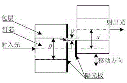
[0042] Such as figure 1As shown, the transmission-type intensity modulation optical fiber displacement sensor includes a fixed optical fiber and a moving optical fiber corresponding to the fixed optical fiber, and the fixed optical fiber and the moving optical fiber are both composed of a cladding and a core embedded in the cladding. A light barrier is provided between the optical fiber and the moving optical fiber. The light barrier is provided with a light-transmitting hole for the light source to transmit from the core of the fixed optical fiber to the core of the moving optical fiber. There are two light barriers, which are respectively arranged on The fixed fiber and the moving fiber are adjacent to the two cross-sections.

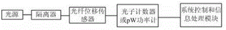
[0043] by figure 1 The transmissive intensity-modulated optical fiber displacement sensor shown is used to form a image 3 The sensor system based on the transmission intensity modulation optical fiber displacement sensor shown, its system archite...

Embodiment 2

[0045] Such as figure 1 As shown, the transmission-type intensity modulation optical fiber displacement sensor includes a fixed optical fiber and a moving optical fiber corresponding to the fixed optical fiber, and the fixed optical fiber and the moving optical fiber are both composed of a cladding and a core embedded in the cladding. A light barrier is provided between the optical fiber and the moving optical fiber. The light barrier is provided with a light-transmitting hole for the light source to transmit from the core of the fixed optical fiber to the core of the moving optical fiber. There are two light barriers, which are respectively arranged on The fixed fiber and the moving fiber are adjacent to the two cross-sections.

[0046] by figure 1 The transmissive intensity-modulated optical fiber displacement sensor shown is used to form a Figure 4 The sensor system based on the transmission intensity modulation optical fiber displacement sensor shown, its system archi...

Embodiment 3

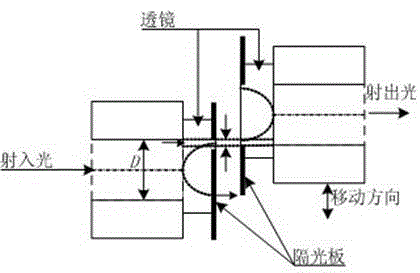
[0048] Such as figure 2 As shown, the optical fiber displacement sensor perpendicular to the axial direction includes a fixed optical fiber and a moving optical fiber corresponding to the fixed optical fiber, and the fixed optical fiber and the moving optical fiber are both composed of a cladding and a core embedded in the cladding. A light barrier is provided between the fixed optical fiber and the moving optical fiber, and the light insulating plate is provided with a light transmission hole for transmitting the light source from the core of the fixed optical fiber into the core of the moving optical fiber. The two cross-sections are respectively provided with lenses, and at this time, the two light barriers are respectively arranged on the two adjacent cross-sections of the two lenses.

[0049] by figure 2 The optical fiber displacement sensor that moves vertically to the axis is shown to form a image 3 The sensor system based on the axial and vertical moving optical f...


PUM


Abstract

The invention discloses an optical fiber displacement sensor, which comprises fixed optical fiber and movable optical fiber corresponding to the fixed optical fiber, wherein the fixed optical fiber and the movable optical fiber are both formed by wrapping layers and fiber cores embedded at the inner parts of the wrapping layers; light isolation plates are arranged between the fixed optical fiber and the movable optical fiber; and light holes used for enabling a light source to be transmitted into the fiber core of the movable optical fiber from the fiber core of the fixed optical fiber are arranged on the light isolation plates. The invention also discloses an intensity modulation type optical fiber displacement sensor system formed by the optical fiber displacement sensor and an application method of the system. By adopting the invention, the problems of low measurement accuracy and low sensitivity of the intensity modulation type optical fiber displacement sensor system existing in the prior art are solved.

Description

technical field [0001] The invention relates to an optical fiber displacement sensor, in particular to an optical fiber displacement sensor, an intensity modulation sensor system based on the optical fiber displacement sensor and an application method of the system. Background technique [0002] The intensity-modulated optical fiber displacement sensor is currently the most widely used optical fiber displacement sensor. Its working principle is to use the disturbance to be measured to change the intensity of the optical signal in the optical fiber, and to realize the measurement of the measured object by measuring the change law of the output light intensity. , because there is a good linear relationship between the disturbance of environmental parameters and the loss of light intensity, the performance of the intensity-modulated optical fiber displacement sensor is relatively stable, and the sensitivity and measurement accuracy are relatively high. [0003] According to the...

Claims


Application Information

Patent Timeline
Patent Type & Authority Patents(China)
IPC IPC(8): G01B11/02
Inventor 熊英蒋久清
Owner CHENGDU LINGGUANG QUANTUM TECH
Why Eureka
Try Eureka