Light path deflecting optical fiber strain sensor based on optical fiber LP21 mode

An optical fiber strain and steering type technology, which is applied in the direction of instruments, optical devices, and measuring devices, can solve the problems of complex structure of optical fiber torsion sensors, inability to measure torsional strain, and poor anti-interference performance, so as to facilitate miniaturization and large-scale production The effect of laying, spot shape stability, and low cost

Inactive Publication Date: 2012-07-25
ZHEJIANG UNIV
View PDF2 Cites 2 Cited by
  • Summary
  • Abstract
  • Description
  • Claims
  • Application Information

AI Technical Summary

Problems solved by technology

However, the first two types cannot measure torsional strain, and have the defects of limited bending radius, complicated equipment, high cost, and poor anti-interference performance.
The fiber optic torsion sensor has a more complicated structure and has the disadvantages mentioned above

Method used


Image

  • Light path deflecting optical fiber strain sensor based on optical fiber LP21 mode
  • Light path deflecting optical fiber strain sensor based on optical fiber LP21 mode
  • Light path deflecting optical fiber strain sensor based on optical fiber LP21 mode

Examples


Embodiment 1

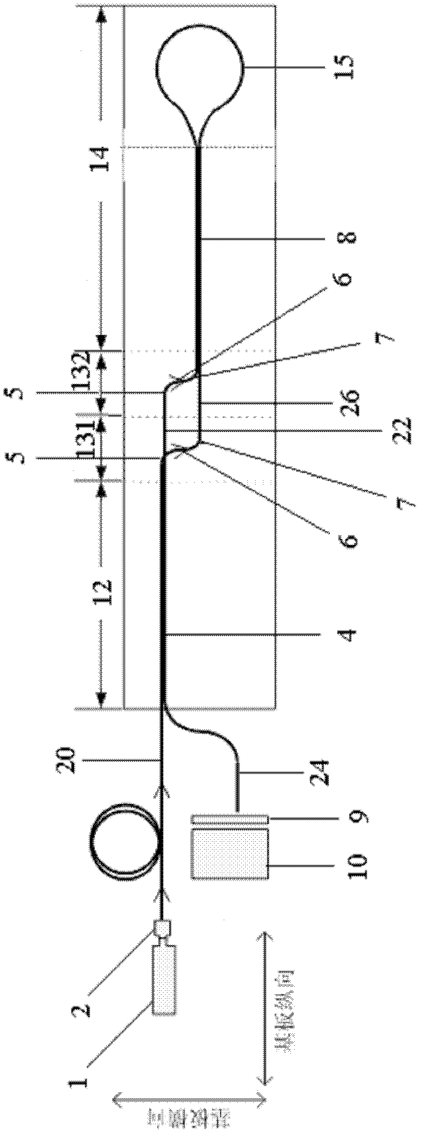
[0032] Such as figure 1 Fiber-based LP shown 21 The optical fiber strain sensor of the present invention comprises an optical fiber light spot generation and sensing device, an optical attenuation sheet 9, a light spot detector 10, a computer, and a substrate. The optical fiber spot generation and sensing device includes a light source 1, a mode selector 2 and a fiber-based LP 21mode optical fiber, the light source 1 is connected to the input end of the mode selector 2, and the output end of the mode selector 2 is connected to the input end of the optical fiber. The optical fiber includes an incident part 4, a sensing part, and an outgoing part 8. The output end of the mode selector 2 is connected to the incident part 4 of the optical fiber, and the sensing part includes a sensing part connected to the incident part 4 of the optical fiber. Part of the input end 5, the sensing portion output end 7 connected to the fiber optic output portion 8, the sensing portion input end 5,...

Embodiment 2

[0050] Such as Figure 5 As shown, the optical fiber strain sensor described in Embodiment 1 can be used together in multiple groups; at this time, the substrate is divided into N+2 parts, and N is the number of optical fiber spot generation and sensing devices fixed on the substrate. The number of sensing parts of the optical fiber is fixed in one-to-one correspondence with the sensing parts of the optical fiber. In this embodiment, multiple groups of optical fiber strain sensors share one light spot detector 10 .

[0051] The measurement method of the present invention is composed of the following steps: 1. Utilize the laser transmitter to generate a beam of laser light and enter the strain sensor through the mode selector 2; 21 The transmission characteristics of the mode process the optical signal; 3. After the optical signal passing through the sensor is processed, it enters the signal processing device, and finally realizes the measurement of the torsion or space curvat...


PUM


Abstract

The invention relates to a light path deflecting optical fiber strain sensor based on an optical fiber LP21 mode, comprising a bendable and twistable substrate, a light spot detector and at least one group of optical fiber light spot generating and sensing devices, wherein each optical fiber light spot generating and sensing device comprises a light source, a mode selector and an optical fiber based on the optical fiber LP21 mode; the optical fiber comprises an incident part, a sensing part and an emergent part; the sensing part comprises a sensing part input end connected with the incident part of the optical fiber and a sensing part output end connected with the emergent part of the optical fiber; the sensing part input end and the sensing part output end are cambered; the incident part is divided into two segments in contact with each other, and the emergent part is also divided into two segments in contact with each other; the sensing part is divided into two segments and the sensing part input end and the sensing part output end are separated from each other; and the two segments of the emergent part are connected through an optical fiber convolution part, thereby realizing the convolution and deflection of the light path.

Description

technical field [0001] The invention relates to an optical fiber sensing device, in particular to an optical fiber LP 21 Mode of optical path steering type fiber optic strain sensor. Background technique [0002] Optical fiber strain sensor refers to a sensor that applies strain to an optical fiber from the outside world and measures the amount of external strain by detecting changes in optical signals. Fiber optic strain sensors mainly include fiber optic bending sensors and fiber optic torsion sensors. Optical fiber bending strain sensing mainly includes microbending sensors based on optical energy loss, bending sensors based on fiber grating characteristics, and bending sensors based on optical fiber spot pattern changes. However, the first two methods cannot measure torsional strain, and have the defects of limited bending radius, complicated equipment, high cost, and poor anti-interference. The optical fiber torsion sensor has a complex structure and has the disadvan...

Claims


Application Information

Patent Timeline
Patent Type & Authority Applications(China)
IPC IPC(8): G01B11/16
Inventor 袁余锋魏婉婷吴兴坤
Owner ZHEJIANG UNIV
Why Eureka
Try Eureka