Device and method for testing forming limit of sheet material in three-dimensional stress state

A sheet metal forming, three-dimensional stress technology, applied in the direction of testing the ductility of the material, can solve the problem that the Nakazima test method cannot meet the blank deformation, etc., and achieve the effect of simple method and easy realization.

Inactive Publication Date: 2012-07-25
HARBIN INST OF TECH
View PDF8 Cites 22 Cited by
  • Summary
  • Abstract
  • Description
  • Claims
  • Application Information

AI Technical Summary

Problems solved by technology

[0004] In view of the fact that the current Nakazima test method for measuring the forming limit cannot meet the actual situation of blank deformation under the three-dimensional stress state, the present invention provides a test device and method for the forming limit of the sheet metal under the three-dimensional stress state. The forming limit under the state, to meet the practical application

Method used


Image

  • Device and method for testing forming limit of sheet material in three-dimensional stress state
  • Device and method for testing forming limit of sheet material in three-dimensional stress state
  • Device and method for testing forming limit of sheet material in three-dimensional stress state

Examples


specific Embodiment approach 1

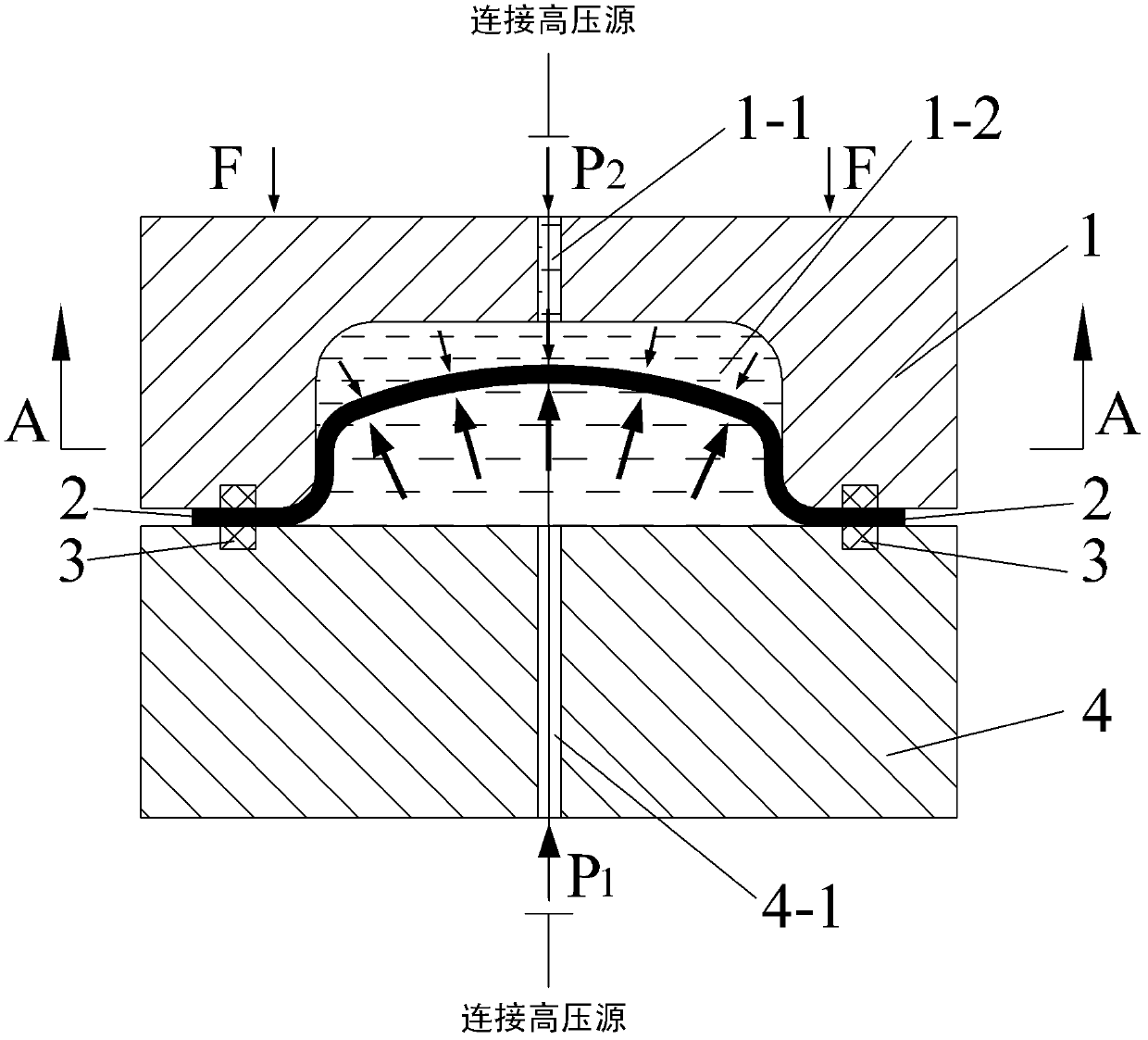
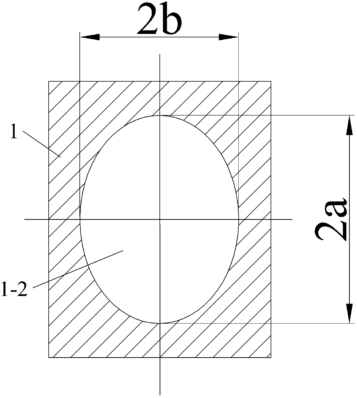
[0021] Specific implementation mode one: as Figure 1-5 As shown, the plate forming limit test device under the three-dimensional stress state described in this embodiment includes an upper mold 1 and a lower mold 4, the inner surface of the cavity 1-2 of the upper mold 1 is an elliptical cylinder, and the upper mold The upper mold liquid injection hole 1-1 communicated with the mold cavity 1-2 is provided on the top of 1; 1, the axis of the liquid injection hole 4-1 of the lower mold, and the centerline of the cavity 1-2 along the length direction are arranged coaxially, and the upper mold 1 and the lower mold 4 are sealed by the sealing ring 3 after mold closing. After the upper mold 1 and the lower mold 4 are closed, the liquid injection hole 4-1 of the lower mold communicates with the opening of the cavity 1-2, and the upper mold 1 is connected with the slider of the press; the lower mold 4 is connected with the press The workbench is connected and fixed; both the upper m...

specific Embodiment approach 2

[0022] Specific implementation mode two: as Figure 1-5 As shown, the test method for sheet metal forming limit under the three-dimensional stress state using the test device described in the first embodiment described in this embodiment is realized according to the following steps:

[0023] Step 1. Prepare multiple sets of test devices according to claim 1. The ratios of the major and minor axes of the elliptical sections of the cavity 1-2 in each test device are different, and the ratios of the major and minor axes of each elliptical cross section are uniformly selected within the range of 1 to 2.5. ;

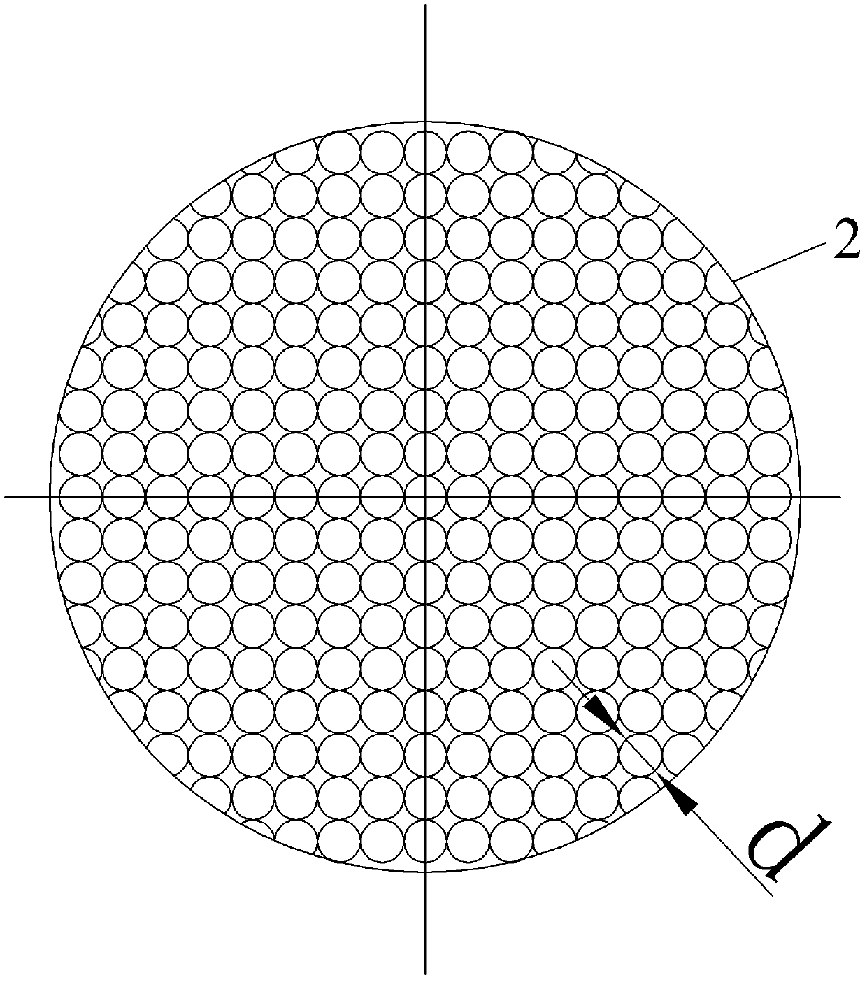
[0024] Step 2, making the metal sheet sample: using electro-corrosion method to make a plurality of circular or square dents arranged in a matrix on the upper surface of the circular metal sheet sample, so that the upper surface of the circular metal sheet sample is Circular grid or square grid arranged in matrix; measure the diameter d of circular or square dents or the sid...

specific Embodiment approach 3

[0034] Specific embodiment three: In this embodiment, seven sets of test devices according to claim 1 are prepared in step one, and the ratios of major and minor axes of the elliptical cross-sections of cavity 1-2 in each test device are respectively 1, 1.2, 1.4, 1.6, 1.8 , 2.0 and 2.5, the minor axis length is 50mm, and the major axis is 50mm, 60mm, 70mm, 80mm, 90mm, 100mm and 125mm respectively; in step 2, the diameter of the circular metal plate sample produced is 200mm. Other steps are the same as in the second embodiment.

[0035] The pressure P in the fluid medium chamber 1-2 (cavity 1-2) 2 It plays the role of applying normal pressure and establishing a three-dimensional stress state. The pressure P in the fluid medium cavity (lower mold liquid injection hole 4-1) 1 Make the sample bulge. This method can not only replace the Nakazima test method to determine the bulging limit, but also evaluate the influence of the normal stress on the forming limit in the three-dimen...


PUM

PropertyMeasurementUnit
diameteraaaaaaaaaa

Abstract

The invention provides a device and a method for testing a forming limit of a sheet material in a three-dimensional stress state, relating to the device and the method which are used for testing the forming limit of the sheet material. Aiming to the problems that the forming limit of the sheet material in the three-dimensional stress state is difficult to test and an influence of normal pressure to the forming limit is difficult to estimate, the device comprises an upper die and a lower die. In a test, a fluid medium is injected into the lower die, a test sample of the sheet material is placed, mold clamping force is applied, the fluid medium is injected into the upper die, and pressurized deformation is carried out by controlling pressure in the upper die and the lower die in sequence. Braking strains of the test sample of the metal sheet material can be calculated according to measured data before and after circular or square mesh deformation, namely epsilon 1=Ln[d1-d/d] and epsilon 2=Ln[d-d2/d]; a plurality of groups of different limit strain data points can be obtained by changing a ratio of a long shaft to a short shaft of an oval cross section of a cavity; and the obtained data points can be connected or fitted by respectively using the epsilon 1 and the epsilon 2 as a transverse coordinate and a vertical coordinate, so as to obtain the sheet material forming limit curve at the three-dimensional stress state at a certain normal pressure condition to estimate the influence of the normal strain to the forming limit in the three-dimensional stress state.

Description

technical field [0001] The invention relates to a device and method for testing the forming limit of a plate under a three-dimensional stress state. Background technique [0002] The forming limit is an important performance index and process parameter in the field of sheet metal forming, reflecting the maximum deformation degree of the sheet before plastic instability. In order to determine the forming limit of sheet tensile instability, many research and evaluation methods have been proposed from the aspects of theory and experiment. Among them, the Nakazima test method is a commonly used method at present, and its essence is a hemispherical rigid punch bulge test. Print a circular grid on the surface of the sample by screen printing, change the width of the sample and the lubrication between the test piece and the punch to carry out the hemispherical rigid punch bulge experiment, after the sample breaks, the grid changes from a circle to a Ellipse, measure the size of t...

Claims


Application Information

Patent Timeline
Patent Type & Authority Applications(China)
IPC IPC(8): G01N3/28
Inventor 徐永超苑世剑
Owner HARBIN INST OF TECH
Why Eureka
Try Eureka