Transparent display device and electronic device applying transparent display device

A technology for transparent display and electronic equipment, which is applied in the field of transparent display devices and electronic equipment using the device, can solve the problems of increasing the manufacturing cost of display devices, and achieve the effects of low cost, simple process, and simple manufacturing process

Active Publication Date: 2012-07-25
HISENSE VISUAL TECH CO LTD
View PDF3 Cites 12 Cited by
  • Summary
  • Abstract
  • Description
  • Claims
  • Application Information

AI Technical Summary

Problems solved by technology

However, the addition of optical sheets and the special design of the light guide plate will increase the manufacturing cost of the display device

Method used


Image

  • Transparent display device and electronic device applying transparent display device
  • Transparent display device and electronic device applying transparent display device
  • Transparent display device and electronic device applying transparent display device

Examples


Embodiment 1

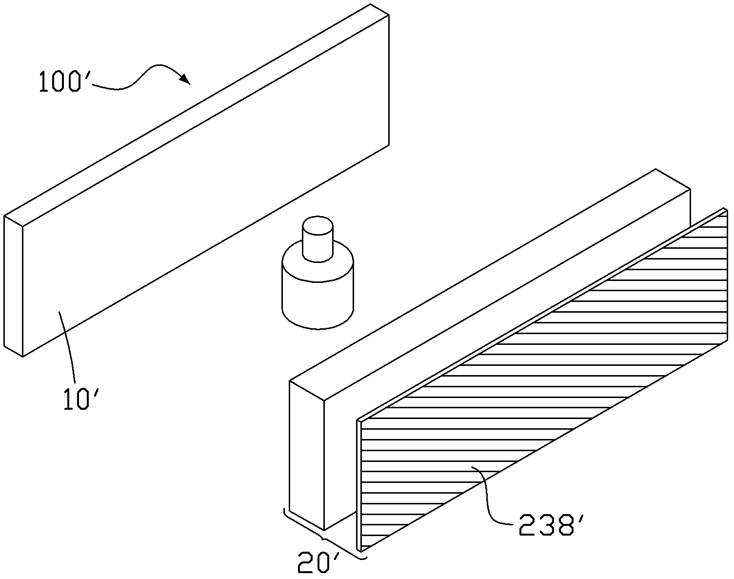
[0028] Please refer to figure 1 , the transparent display device 100' of the second embodiment of the present invention includes a polarized light source 10' and a liquid crystal panel 20'. The polarized light source 10' emits polarized light with a first polarization direction. The polarized light source 10' is located behind the liquid crystal panel 20', which can be directly behind, laterally behind, above the rear or below the rear. In this embodiment, the polarized light source 10' is located directly behind the liquid crystal panel as an example.

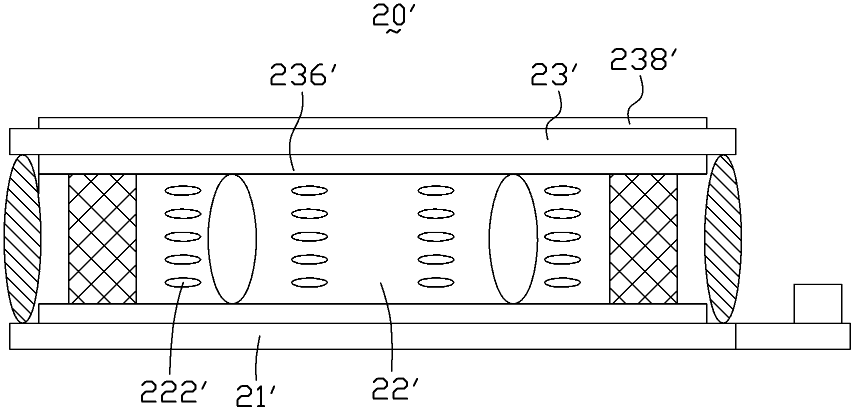
[0029] Please refer to figure 2 , the liquid crystal panel 20' includes a first substrate 21', a liquid crystal layer 22', a second substrate 23' and a driving circuit board 24'. The liquid crystal layer 22' is sandwiched between the first substrate 21' and the second substrate 23'. The driving circuit board 24' is disposed on one side of the first substrate 21'. In a normal state, the alignment direction of the liquid cr...

Embodiment 2

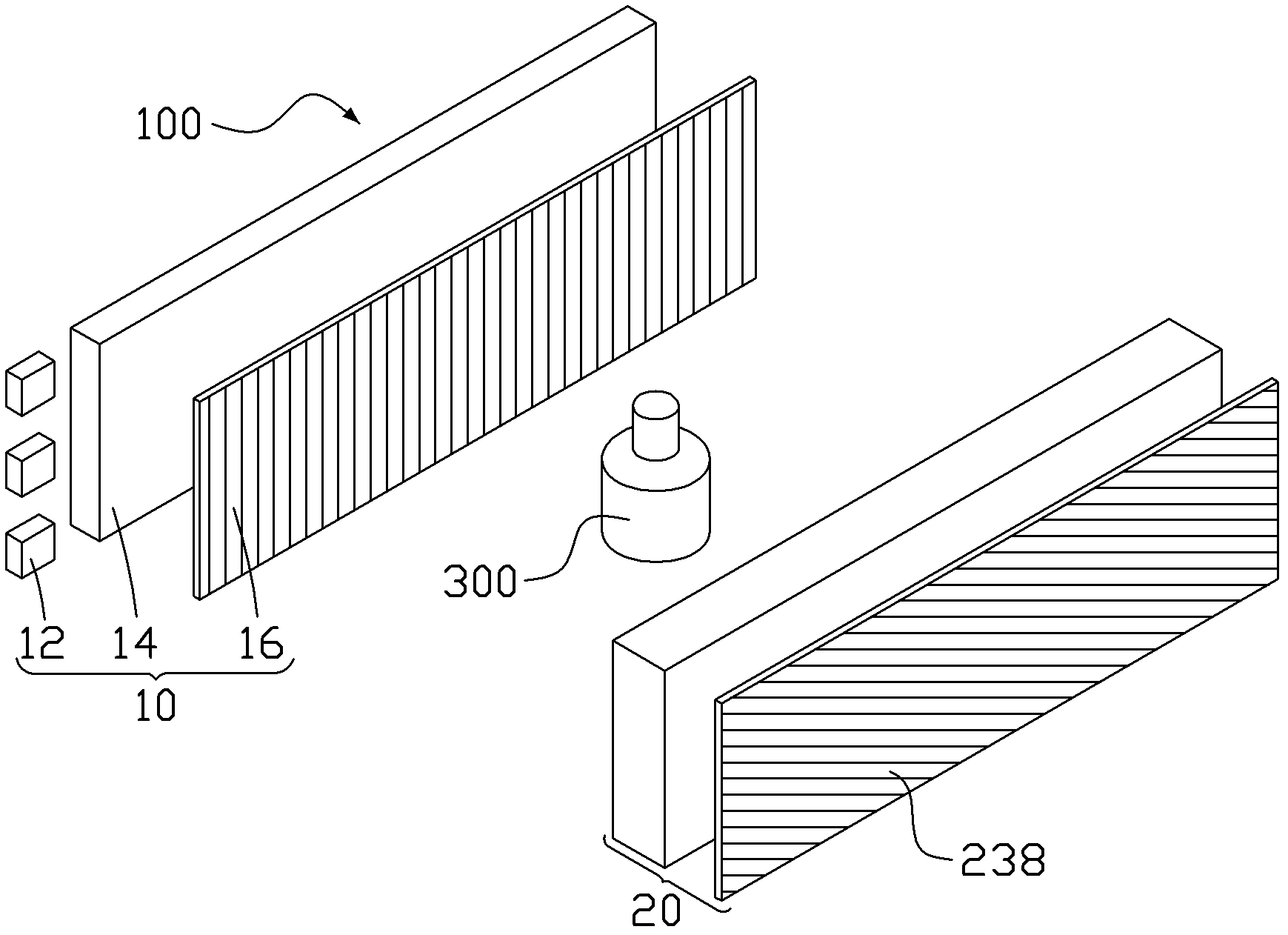
[0037] Please refer to image 3 , the transparent display device 100 of the first embodiment of the present invention includes a backlight module 10 and a liquid crystal panel 20 . The backlight module 10 is located behind the liquid crystal panel 20 , which can be right behind, side behind, upper rear or lower rear. In this embodiment, the backlight module 10 is located right behind the liquid crystal panel as an example for illustration. The backlight module 10 includes a natural light emitting source 12 , a light guide plate 14 and a backlight polarizer 16 . The natural light emitting light source 12 may be a point light source, a line light source or a planar light source. In this embodiment, side light LEDs are selected as the natural light emitting light source 12 . The light guide plate 14 is used to homogenize the light emitted by the LED, and the backlight polarizer 16 is used to polarize the light emitted by the light guide plate 14 to form a polarized light so...

Embodiment 3

[0050] Figure 5 It is a schematic diagram of an electronic device 1 equipped with a transparent display device 100' or 100. The electronic device 1 further includes a housing 200 . The frame body 200 includes a bottom 201 , a surrounding wall 202 and an opening 203 surrounded by the surrounding wall 202 , wherein the opening 203 is opposite to the bottom 201 . The polarized light source 10' / backlight module 10 is located at the bottom 201 or the surrounding wall 202 of the frame body 200, and the liquid crystal panel 20' or 20 covers the opening 203 of the frame body 200. The liquid crystal panel 20' or 20 may partially or completely cover the opening 203 of the frame body 200. Here, the bottom 201 may also be a side wall in a general sense, and the peripheral wall 202 may also include a top wall and a bottom wall in a general sense.

[0051] Preferably, the electronic device 1 may be an exhibition cabinet, and in order to enhance the light effect, the inner side of the pe...


PUM


Abstract

Provides are a transparent display device and an electronic device applying the transparent display device. The transparent display device comprises a liquid crystal display panel and a polarization light source, the liquid crystal display panel comprises a first substrate, a second substrate and a liquid crystal layer clamped between the first substrate and the second substrate, and the polarization light source is located at the rear of the liquid crystal display panel. When the liquid crystal display panel displays images, polarized light emitted by the polarization light source passes through the liquid crystal layer and then passes through an upper polaroid. Compared with the prior art, the transparent display device and the electronic device applying the transparent display device have the advantages of being low in cost, simple in process and high in color gamut.

Description

technical field [0001] The invention relates to a display device, in particular to a transparent display device and electronic equipment using the same. Background technique [0002] In liquid crystal display, transparent display is an emerging display technology. This technology requires that when the LCD screen is displaying a picture, the items placed behind it can be seen through the LCD screen at the same time. This requires the LCD screen to maximize the penetration rate of the LCD screen without losing its color gamut and contrast, so that the viewer can clearly see the items behind the screen during the display. [0003] CN102096237A discloses a transparent display device. In order to improve the brightness in the image mode, an optical sheet is arranged on the lower part of the light guide plate to reflect the light emitted from the light guide plate to the lower part and provide the reflected light to the light guide plate again. In order to allow natural light t...

Claims


Application Information

Patent Timeline
IPC IPC(8): G02F1/13357G02F1/1335A47F11/06A47F11/10F25D29/00
Inventor 徐爱臣黄顺明孙明
Owner HISENSE VISUAL TECH CO LTD
Why Eureka
Try Eureka