
Single finger print collecting device

A fingerprint collection and fingerprint technology, which is applied to lighting devices, components of lighting devices, light sources, etc., can solve the problems of fingerprint collection rate and recognition accuracy need to be further improved, shorten the longitudinal size of the fingerprint collector, and is not easy to carry, etc., to achieve Improve fingerprint collection rate and recognition accuracy, reduce distortion, and save costs

Active Publication Date: 2012-07-25
DONGGUAN ZKTECO ELECTRONICS TECH
View PDF3 Cites 8 Cited by
  • Summary
  • Abstract
  • Description
  • Claims
  • Application Information

AI Technical Summary

Problems solved by technology

This kind of small fingerprint collector uses a flat mirror for total reflection, and the optical path is a broken line. Compared with a straight optical path, the longitudinal size of the fingerprint collector can be significantly shortened, which is conducive to the miniaturization of the device. However, the volume is still large and not easy to carry. It does not have the functions of combining with a computer to complete the user's single-fingerprint collection, single-fingerprint comparison, abnormal alarm, and control signal output. The fingerprint collection rate and recognition accuracy need to be further improved, and the size of the living single-fingerprint collection window does not meet the requirements of Chinese public security. The department and the Federal Bureau of Investigation (FBI) must be larger than 12.8mm×16.5mm, the image resolution is 500dpi, and the image gray level is 256gray-level.

Method used


Image

  • Single finger print collecting device
  • Single finger print collecting device
  • Single finger print collecting device

Examples


Embodiment Construction

[0035] The present invention will be described below in conjunction with specific embodiments and with reference to the accompanying drawings.

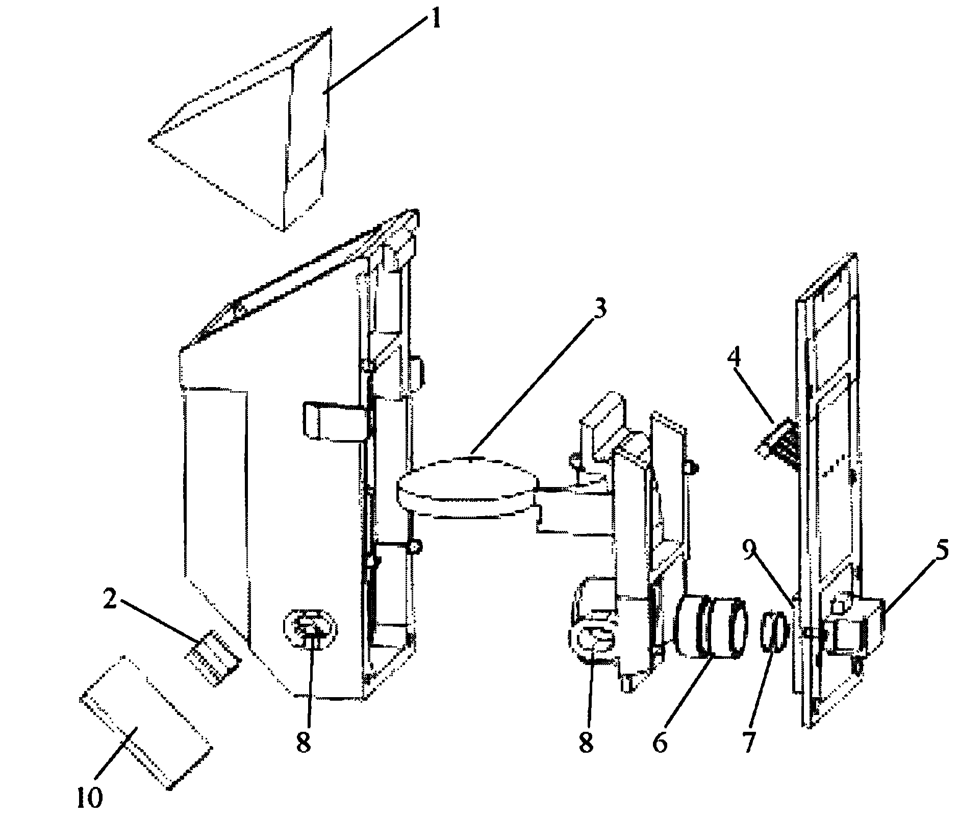
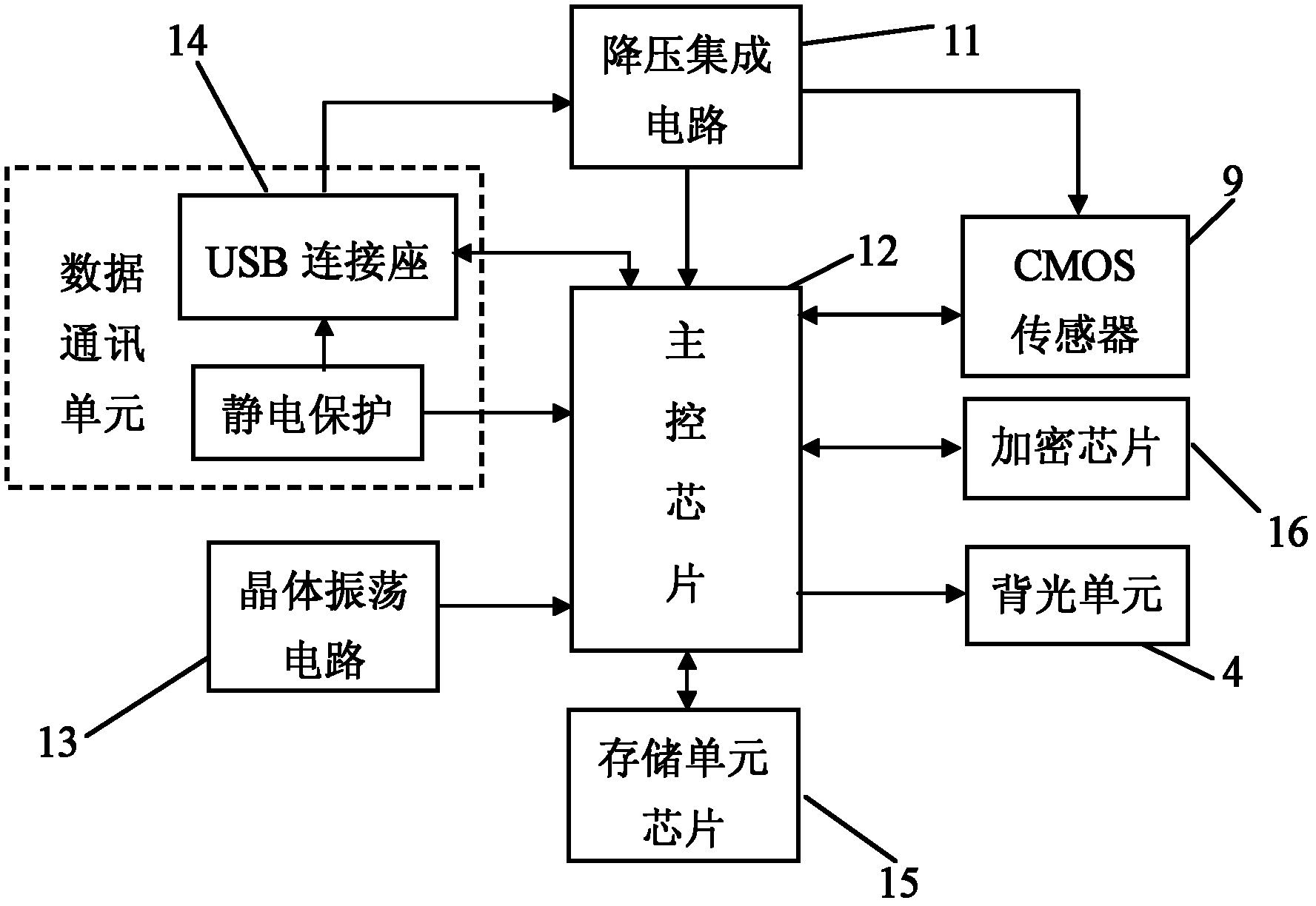
[0036] such as Figures 1 to 3 The shown single-finger fingerprint collection device includes a casing, an optical single-finger fingerprint imaging module disposed in the casing, and a backlight unit 4 .

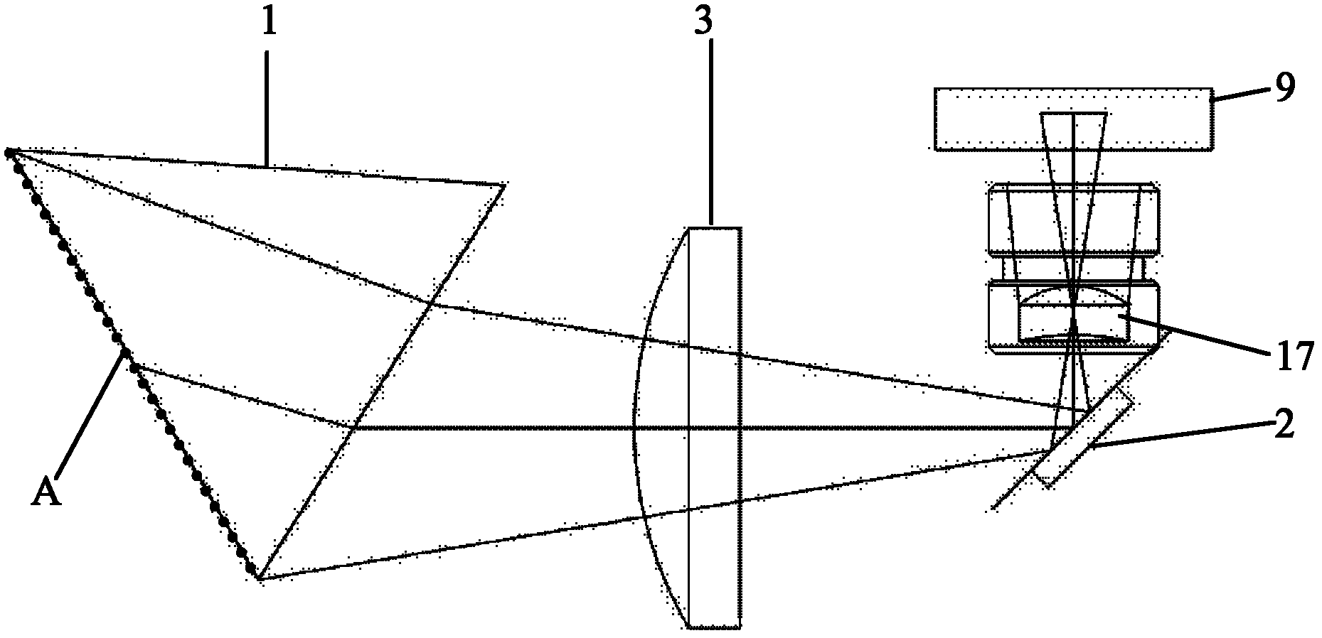
[0037]The optical fingerprint imaging module includes a prism, an imaging component, an image acquisition unit and a light source arranged in accordance with the optical path. The prism is a triangular prism 1, including a large end face, a small end face and a lower side face parallel to each other, and the large end face is larger than 12.8mm× The 16.5mm single-finger fingerprint image acquisition surface A is the living single-finger fingerprint acquisition window. The small end surface is the incident surface of the light source, and the lower side is the imaging surface opposite to the imaging. The optical path between the tri...


PUM

PropertyMeasurementUnit
Spacingaaaaaaaaaa
Image resolutionaaaaaaaaaa

Abstract

The invention relates to a single finger print collecting device, which is an improvement on a small finger print collecting device disclosed in the prior patent with a number of CN102043947A. A concave-convex lens is arranged between a prism of an optical single finger print imaging module and a light path between plane mirrors; the convex surface of the concave-convex lens is opposite to the prism; the area of the large end surface of the prism, namely a living person single finger print collecting window, is larger than the product of 12.8mm and 16.5mm; a CMOS (complementary metal-oxide-semiconductor) sensor has the pixel of at least 8,215; an optical system, a circuit control module and a shell have the characteristic of small size; the cost of the single finger print collecting device is further saved, and the single finger print collecting device is convenient to carry, can be used together with a computer to finish the user single finger print collecting, the single finger print comparing, the abnormal alarming and the control signal outputting, and improves the finger print collecting speed and identifying accuracy significantly; and the living person single finger print collecting window size, the image resolution and image gray level meet the requirements of the Chinese public security department and the Federal Bureau of Investigation in America.

Description

technical field [0001] The invention relates to a method or device for biometric identification using electronic circuits, in particular to a single-finger fingerprint collection device. Background technique [0002] The volume of the existing optical single-finger fingerprint collection device is generally large. The applicant's prior patent CN102043947A discloses "A Small Fingerprint Collector", which includes a casing and an optical fingerprint imaging module arranged in the casing. The optical fingerprint imaging module includes a prism, an imaging objective lens, an image acquisition unit and a light source that are arranged in accordance with the optical path. The prism is a uniform and symmetrical six-sided trapezoid prism with a longitudinal section base greater than its height, including large end faces parallel to each other and facing each other. , the small end face, the lower side and the other three sides, the large end face is the image acquisition face, the s...

Claims


Application Information

Patent Timeline
IPC IPC(8): G06K9/00G06K9/20F21V13/04F21Y101/02F21Y115/10
Inventor 车全宏李治农杨辰晓
Owner DONGGUAN ZKTECO ELECTRONICS TECH
Learn More