
Polar post and lead bushing structure and fusion welding method as well as storage battery employing structure

A pole and welding technology, applied to structural parts, battery pack parts, circuits, etc., can solve the problems of poor welding quality, difficult inspection, small welding area, etc., to improve battery quality and life, prevent melting phenomenon, and ensure The effect of weld strength

Active Publication Date: 2014-07-02
ANHUI LEOCH BATTERY TECH
View PDF2 Cites 1 Cited by
  • Summary
  • Abstract
  • Description
  • Claims
  • Application Information

AI Technical Summary

Problems solved by technology

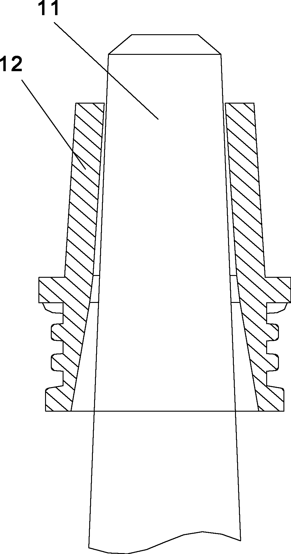
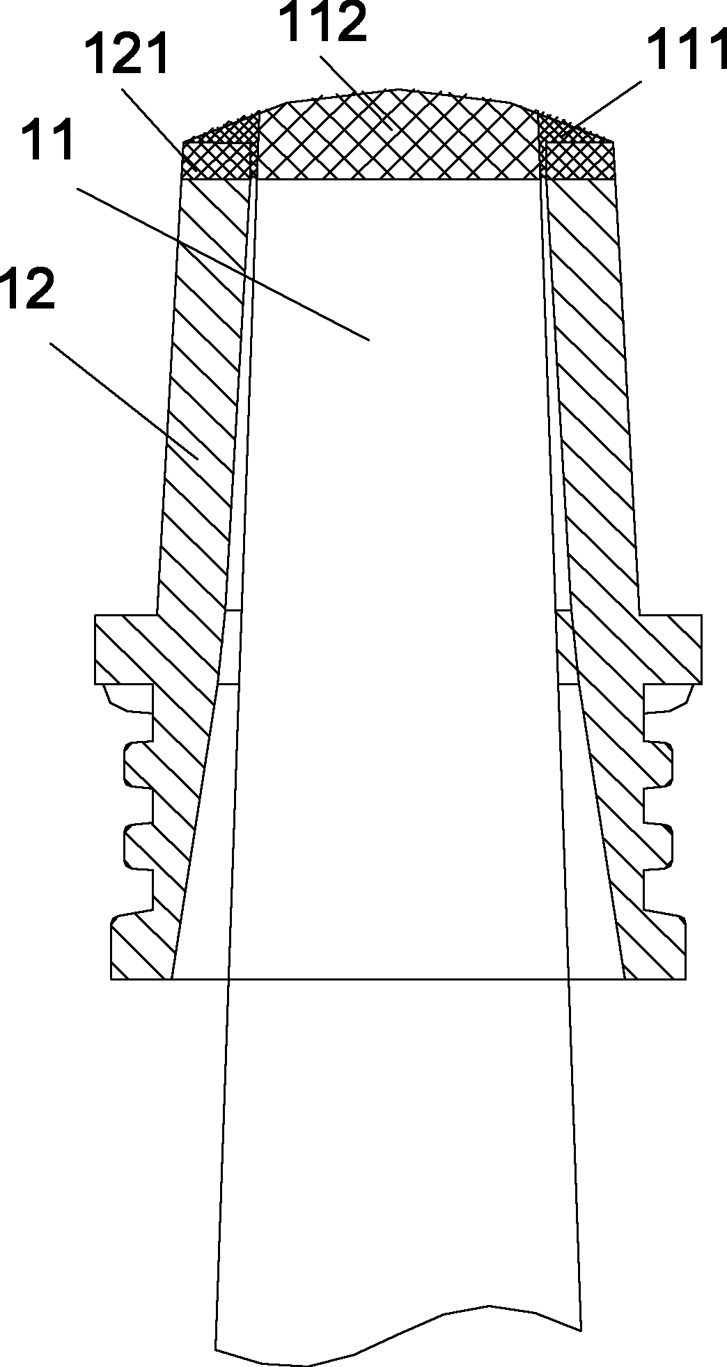
However, on the one hand, the improvement effect of the process control is not enough, and its welding area does not fully meet the process requirements, and this process control has high requirements for operators. The middle position of the welding pole makes the cold lead of the pole quickly bury the gap between the pole and the lead sleeve, resulting in such Figure 4 The welding effect, the welding area in the figure only includes the pole welding area 112 and the welding body area 111, so that the welding area between the lead sleeve 12 and the pole 11 is small, the welding quality is poor, and it is difficult to inspect during the production process. The welding area of ​​the column melts and leaks lead when a large current is discharged or the car is started. After the lead is leaked, a short circuit is likely to occur, so that there may be a hidden danger of battery fire, resulting in a large number of defective products

Method used


Image

  • Polar post and lead bushing structure and fusion welding method as well as storage battery employing structure
  • Polar post and lead bushing structure and fusion welding method as well as storage battery employing structure
  • Polar post and lead bushing structure and fusion welding method as well as storage battery employing structure

Examples


Embodiment 1

[0031] In an embodiment of the present application, a structure of a pole and a lead sleeve includes a lead sleeve, a pole, and a welded body formed by welding the pole. The gap between the pole and the hole of the lead sleeve is matched to facilitate the assembly of the pole and the lead sleeve, but the matching gap is small, usually about 0.2mm, to prevent lead leakage during the welding process. The welding end of the pole passes through the sleeve hole, and the inner hole wall at the upper end of the sleeve hole and the outer peripheral surface of the pole surround to form a welding groove with an upper opening. The welding body is distributed on the surface of the pole, the surface of the lead sleeve and the welding groove, and welds the pole and the lead sleeve into one body.

[0032] In this example, the flowing melt produced by the welding process on the upper end of the pole is mainly distributed on the surface of the welding end of the pole, the upper surface of the ...

Embodiment 2

[0040] The application also discloses a welding method of a pole and a lead sleeve, the welding method comprising:

[0041] Step a, matching the gap between the pole and the sleeve hole of the lead sleeve, the upper end of the pole passes through the sleeve hole, and the inner hole wall at the upper end of the sleeve hole and the outer peripheral surface of the pole are enclosed to form a welding groove;

[0042] Step b, welding the pole so that the upper end of the pole forms a welded body (the welded body is defined the same as in Embodiment 1), and the welded body is distributed on the surface of the pole, the surface of the lead sleeve and the welding groove, and the pole and the lead The sleeve is welded into one and fixed.

[0043] In this example, the welding groove is arranged around the pole, and its number can be one or more. For example, the welding groove can be one or more arc-shaped grooves or square grooves arranged around the pole, or only one Set of ring groo...

Embodiment 3

[0048] The present application also discloses a pole and lead sleeve structure manufactured according to the welding method described in the third embodiment above.


PUM


Abstract

The invention relates to a polar post and lead bushing structure and a fusion welding method as well as a storage battery employing the structure. The polar post and lead bushing structure comprises a lead bushing, a polar post and fusion welding bodies formed by welding the polar post, wherein the polar post and a bushing hole of the lead bushing are in clearance fit, a fusion welding end of the polar post penetrates out from the bushing hole, an inner hole wall at the upper end of the bushing hole and an outer peripheral face of the polar post form a fusion welding groove with an upper opening in an enclosure manner, and the fusion welding bodies are distributed on the surface of the polar post, the surface of the lead bushing and the interior of the fusion welding groove so as to connecting the polar post and the lead bushing into a whole through fusion welding. According to the invention, the fusion welding groove is arranged between the outer peripheral face of the polar post and the inner hole wall at the upper end of the bushing hole of the lead bushing, and flowing fusant produced during fusion welding of the polar post flows into the fusion welding groove to increase the fusion welding area between the polar post and the lead bushing. Upon differences in the depth and size of the fusion welding grooves, the finally formed fusion welding areas are different, so that an operator can design the depth and size of the fusion welding groove according to the needs of a practical situation so as to meet different technological requirements.

Description

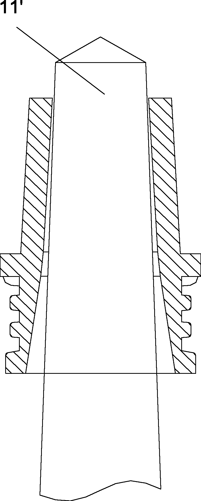
technical field [0001] The invention relates to the field of accumulator manufacturing, in particular to a pole and lead sleeve structure and welding method, and an accumulator applying the structure. Background technique [0002] In the manufacturing process of batteries, the welding process of lead sleeves and positive and negative poles is very important, especially for batteries that need to be discharged with high current. For example, in the production process of automobile batteries, if the welding and welding of positive and negative poles and lead sleeves If the quality is not good, the welding area is small, which will lead to poor conductivity, and it will easily melt when a large current is discharged or when the car is started. [0003] Please refer to figure 1 and figure 2 , the structure of the pole and the lead sleeve used in the existing vehicle battery is usually two kinds, one such as figure 1 As shown, the pole 11 and the lead sleeve 12 are in clearan...

Claims


Application Information

Patent Timeline
Patent Type & Authority Patents(China)
IPC IPC(8): H01M2/30
CPCY02E60/10
Inventor 熊正林王治宏张祥
Owner ANHUI LEOCH BATTERY TECH
Learn More