
Manufacturing structure of rotary opposite-cutting saw blades

A technology of saw blades and cutting saws, which is applied in the field of manufacturing structure of rotary counter-cut saw blades, which can solve problems such as danger, stacking, broken teeth, personal safety, etc., to improve effective impact resistance strength, increase contact area, and optimize angle design Effect

Inactive Publication Date: 2012-08-01
SUZHOU TINGENS IISAW TECH
View PDF11 Cites 0 Cited by
  • Summary
  • Abstract
  • Description
  • Claims
  • Application Information

AI Technical Summary

Problems solved by technology

[0004] As a result, the friction ring or the friction boss generates heat due to friction, and the wear of the wear-resistant ring or the boss will cause the inner saw blade to not be positioned reliably, making the inner saw blade and the outer saw blade loose, so that the inner saw blade and the outer saw blade More reliable positioning and pressing are not obtained, and manufacturing errors are added; rotation jump and swing are unavoidable. The consequence is that when the outer saw blade and the inner saw blade rotate in opposite directions, the friction between the saw blades generates heat, interference and collision. At the same time, It will also cause the materials to be cut to pile up between the outer saw blade and the inner saw blade; cause broken teeth and even cause personal safety hazards and other adverse consequences

Method used


Image

  • Manufacturing structure of rotary opposite-cutting saw blades
  • Manufacturing structure of rotary opposite-cutting saw blades
  • Manufacturing structure of rotary opposite-cutting saw blades

Examples


Embodiment Construction

[0017] The preferred embodiments of the present invention are described in detail below, so that the advantages and features of the present invention can be more easily understood by those skilled in the art, so as to define the protection scope of the present invention more clearly.

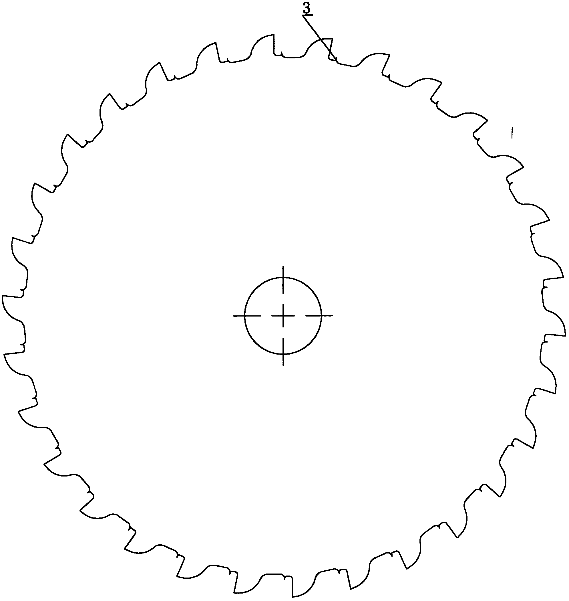
[0018] See attached figure 1 , is a structural schematic diagram of an embodiment of a manufacturing structure of a rotary counter-cut saw blade according to the present invention. A manufacturing structure of a rotary half-cut saw blade in the present invention includes an outer saw blade 1 and an inner saw blade 2; the outer saw blade 1 is composed of an outer saw blade body 11 and a welding knife tooth 12; the welding knife tooth 12 is welded on Inside the "L" shaped tooth seat on the circumference of the outer saw blade body 11. The inner saw blade 2 is composed of an inner saw blade body 21 and a welding knife tooth 12; One side of the outer saw blade body 11 is the working surface A1, th...


PUM


Abstract

The invention discloses a manufacturing structure of rotary opposite-cutting saw blades. The manufacturing structure comprises an outer side saw blade and an inner side saw blade. The outer side saw blade consists of an outer side saw blade body and welding cutter teeth; and the inner side saw blade consists of an inner side saw blade body and welding cutter teeth. The manufacturing structure is characterized in that at one side of the working face of the outer side saw blade, the welding cutter teeth are parallel to or lower than the working face and are not allowed to be convex; at one side of the cutting face of the outer side saw blade, the welding cutter teeth are higher than the cutting face to form a secondary cutting blade; at one side of the working face of the inner side saw blade, the welding cutter teeth are parallel to or lower than the working face and are not allowed to be convex; at one side of the cutting face of the inner side saw blade, the welding cutter teeth are higher than the cutting face to form the secondary cutting blade. The manufacturing structure of the rotary opposite-cutting saw blades, provided by the invention, is stable and reliable. The manufacturing structure is applicable to manufacturing a composite saw blade mounted on a cutting machine with double saw blades, and is used for sawing and cutting various materials.

Description

technical field [0001] The invention belongs to the field of rotary sawing tools, and relates to a manufacturing structure of a rotary counter-cut saw blade, which is especially suitable for installation on rotary counter-cut electric circular saws, miter saws, and gasoline-powered chop saws, and is used for metal, stone, and wood , cutting of plastic profiles, plates, etc., and sawing and breaking of various materials at the scene of emergency rescue and disaster relief. Background technique [0002] The rotary counter saw is driven by the concentric output shaft of the transmission device to drive the outer saw blade and the inner saw blade at the same time, one rotates clockwise and the other rotates counterclockwise, thereby generating a counter-rotating cutting motion. Since the sawing directions of the outer saw blade and the inner saw blade are opposite, the outer saw blade and the inner saw blade can balance the reaction force of the material to be cut during cutting...

Claims


Application Information

Patent Timeline
Patent Type & Authority Applications(China)
IPC IPC(8): B23D61/04
Inventor 温庆普
Owner SUZHOU TINGENS IISAW TECH
Learn More