
Valve grinding and maintaining machine tool

A grinding and valve technology, applied in the direction of grinding machines, grinding/polishing equipment, metal processing equipment, etc., can solve the problems of poor working strength, poor mechanical properties and rigidity, and too simple structure, and achieve strong rigidity and good mechanical properties Effect

Inactive Publication Date: 2012-08-01
深圳链合科技投资有限公司
View PDF7 Cites 21 Cited by
  • Summary
  • Abstract
  • Description
  • Claims
  • Application Information

AI Technical Summary

Problems solved by technology

[0002] At present, the structural principles and installation forms of existing valve maintenance machines in my country are different. There are portable valve maintenance grinding machines with brackets installed on valves, and there are also machines with valves placed under the cantilever for maintenance, and motors are installed on machines with bearings. The direct-mounted valve repair machine directly fixed on the valve (these three types of equipment are hereinafter referred to as the valve repair grinder), such as utility model patent 00249416.7, utility model patent 200720086019, utility model patent 200720193798.1, generally speaking, This kind of equipment is practical and effective for grinding the valve sealing surface, but there are still some shortcomings, such as too simple structure, poor mechanical properties and rigidity, and poor working strength. It can only grind and repair the valve sealing surface instead of It is possible to complete the surfacing repair of the valve sealing surface through the process from rough surfacing grinding to precision grinding like a valve grinding and maintenance machine tool

Method used


Image

  • Valve grinding and maintaining machine tool
  • Valve grinding and maintaining machine tool
  • Valve grinding and maintaining machine tool

Examples


Embodiment Construction

[0057] The present invention will be further described below in conjunction with the accompanying drawings and specific embodiments.

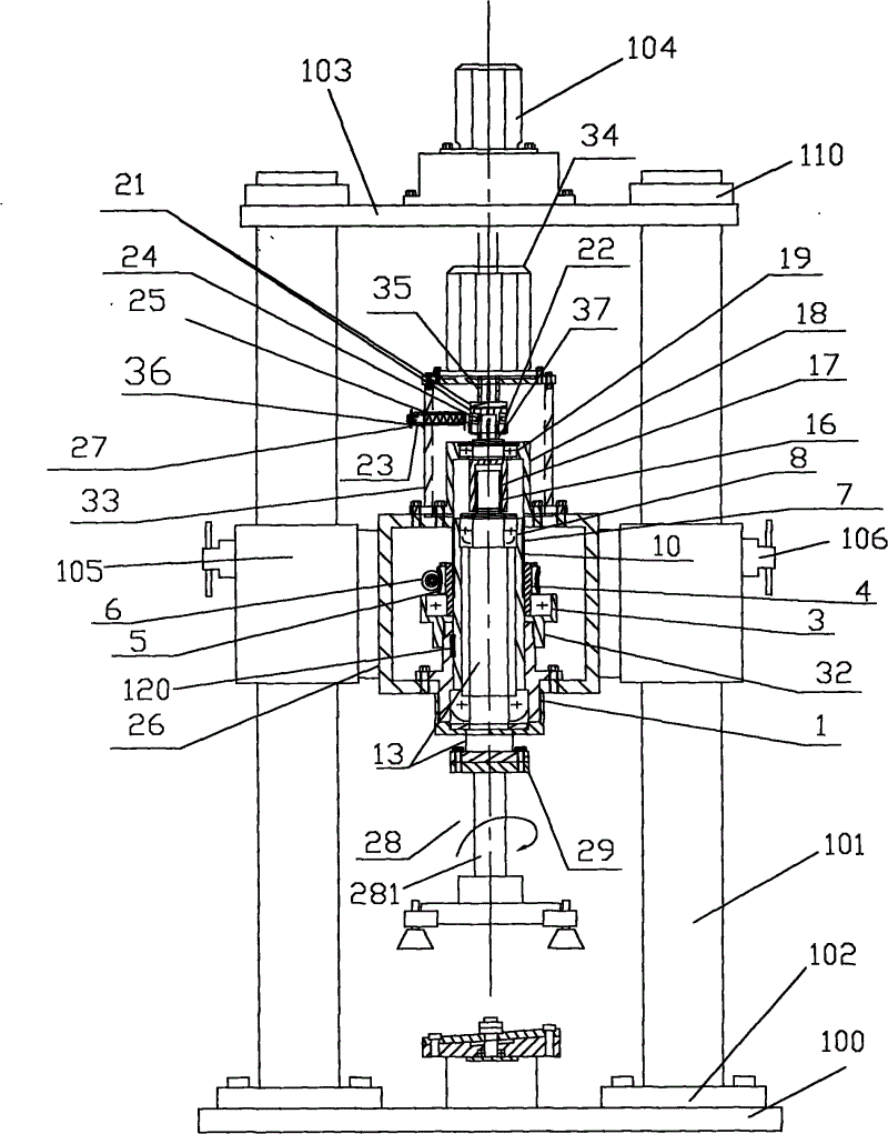
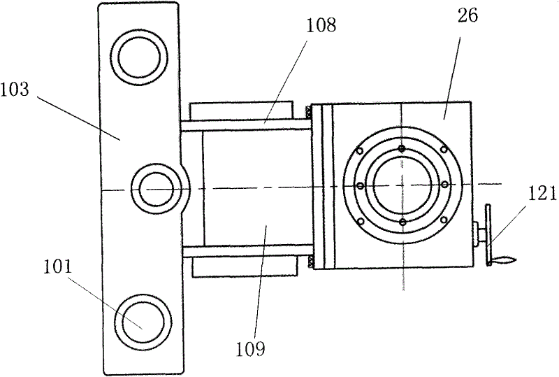
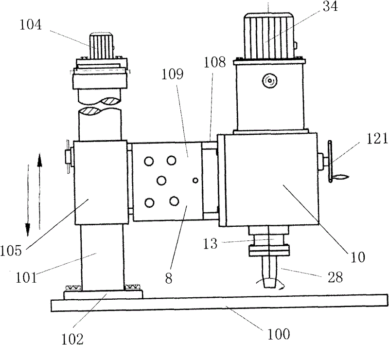
[0058] Such as figure 1 , figure 2 , image 3 , Figure 4 As shown, the valve grinding and maintenance machine tool of the present invention has a workbench 100. Columns 101 are respectively arranged on both sides of the workbench 100. The chassis 102 at the bottom of the column 101 is fixed on the workbench 100 with screws and reinforced with taper pins. The upper ends of the columns 100 are connected with lifting beams 103, and the two ends of the lifting beams 103 are respectively sleeved on the upper ends of the two columns 101, and compressed with lock nuts. The function of 103 on the lifting beam is to carry Figure 4 Lifting mechanism shown. Two upright posts 101 are provided with upright sleeve 105 respectively, and upright sleeve 105 is provided with upright locker 106, and so-called upright locker 106 is a screw rod that is scre...


PUM


Abstract

The invention provides a valve grinding and maintaining machine tool which is provided with a worktable; columns are respectively arranged on two sides of the worktable; the upper ends of the two columns are connected through a lifting cross beam; a lifting motor is connected with a lifting screw rod; and a tool fixture is arranged on the worktable. The valve grinding and maintaining machine tool is characterized in that column sleeves are respectively sleeved on the two columns, and connected through a back plate; the lower end of the lifting screw rod is screwed into a lifting nut fixed on the back plate; a box body is arranged on a support arm on the back plate; a transmission motor is arranged above the box body; a shaft of the transmission motor is connected with a transmission shaft passing through the box body; and a grinding mechanism is connected with the lower end of the transmission shaft fixedly and rigidly. The valve grinding and maintaining machine tool has the advantages that the bearing load is large, the rigidity is high, the strength is high, the stack welding repair is conducted to a valve sealing surface, and the process from stack welding coarse grinding to fine grinding is completed.

Description

technical field [0001] The invention specifically relates to a valve sealing surface maintenance equipment, in particular to a valve grinding and maintenance machine tool with compatible rough grinding and fine grinding functions, which can grind the valve sealing surface after surfacing welding with stainless steel electrodes and hard alloy electrodes. Background technique [0002] At present, the structural principles and installation forms of existing valve maintenance machines in my country are different. There are portable valve maintenance grinding machines with brackets installed on valves, and there are also machines with valves placed under the cantilever for maintenance, and motors are installed on machines with bearings. The direct-mounted valve repair machine directly fixed on the valve (these three types of equipment are hereinafter referred to as the valve repair grinder), such as utility model patent 00249416.7, utility model patent 200720086019, utility model p...

Claims


Application Information

Patent Timeline
IPC IPC(8): B24B19/00
Inventor 万永康张素英
Owner 深圳链合科技投资有限公司
Learn More