Photoprocessing grinding head stress state monitoring device

A force state and monitoring device technology, which is applied in metal processing equipment, manufacturing tools, grinding machine parts, etc., can solve the problems of force changes on the grinding head, poor polishing effect, uneven force, etc.

Inactive Publication Date: 2012-08-01
CHANGCHUN INST OF OPTICS FINE MECHANICS & PHYSICS CHINESE ACAD OF SCI
View PDF6 Cites 0 Cited by
  • Summary
  • Abstract
  • Description
  • Claims
  • Application Information

AI Technical Summary

Problems solved by technology

In the actual processing process, due to the error of the machine tool, assembly or workpiece itself, it is inevitable that the overall force of the grinding head will change or the force will be uneven, and this will change the shape of the removal function, and finally make the polishing The effect becomes worse

Method used


Image

  • Photoprocessing grinding head stress state monitoring device
  • Photoprocessing grinding head stress state monitoring device
  • Photoprocessing grinding head stress state monitoring device

Examples


Embodiment 1

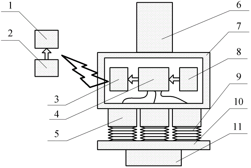
[0011] Embodiment 1: as figure 1 As shown, a device for monitoring the force state of an optical processing grinding head of the present invention includes a display element 1, a signal transmission system, three load cells 5, a connector 6, a frame 7, a power supply 8, three bellows 9, A grinding head seat 10 and a grinding head 11, the grinding head 11 is arranged directly under the grinding head seat 10, each of the bellows 9 is glued together with each of the load cells 5, and three sets of bellows 9 It is arranged on the circumference of the grinding head seat at 120°, the load cell 5 is arranged under the frame 7, the signal transmission system is a wireless communication unit, and the wireless communication unit includes a display element 1, a wireless receiver 2, a wireless Transmitter 3, signal processor 4 and power supply 8, described wireless transmitter 3 is connected with signal processor 4, signal processor 4 is connected with power supply 8 and three are arrange...

Embodiment 2

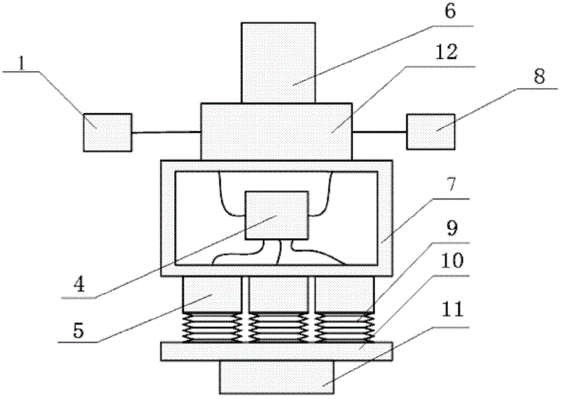
[0013] Embodiment 2: as figure 2 As shown, the signal transmission system in the device for monitoring the stressed state of an optical processing grinding head in the present invention is a wired communication unit, which includes a display element 1, a conductive slip ring 12, a power supply 8, and a signal processing system 4. The signal processing system 4 is arranged inside the frame, the display 1, the power supply 8 and the conductive slip ring 12 are arranged outside the frame 7, and the conductive slip ring 12 is arranged on the top of the frame 7, and the display 1 and the power supply 8 are respectively connected to the conductive The slip rings 12 are connected, and the connecting member 6 is arranged directly on the conductive slip ring 12 .

[0014] In this embodiment, the signal transmission system is changed to be transmitted in a wired manner.

[0015] In this embodiment, a conductive slip ring 12 is added, which is a hollow shaft type conductive slip ring, ...


PUM


Abstract

The invention discloses a photoprocessing grinding head stress state monitoring device, relates to the technical field of optical cold processing, and provides a photoprocessing grinding head stress state monitoring device which provides a necessary means for guaranteeing processing quality. The device comprises a display unit, a signal transfer system, three force sensors, a connector, a frame, a power source, three bellows, a grinding head base and a grinding head, wherein the grinding head is arranged under the grinding head base, each bellows is cemented with each force sensor, the three groups of bellows are arranged on the circumference of the grinding head base at 120 degrees, the force sensors are arranged under the frame, and the connector is arranged above the frame. The device disclosed by the invention can be used for monitoring the stress state of the grinding head on line in real time in the processing process, and at the same time data is sent out and displayed through a data transmission system, so that the data is observed by an operator or is used as the reference for grinding head posture adjustment, and the necessary means is provided for guaranteeing the processing quality.

Description

technical field [0001] The invention relates to the technical field of optical cold processing, in particular to a device for monitoring the force state of an optical processing grinding head. Background technique [0002] The idea of ​​computer-controlled aspheric processing technology (CCOS) was first proposed by the American ltek company in the early 1970s. According to the quantitative surface shape detection data, on the basis of the process control model, it uses a computer to control a small grinding head (the diameter is usually less than 1 / 4 of the workpiece diameter) to grind or polish the optical parts. By controlling the grinding head on the workpiece The dwell time on the surface and the relative pressure between the grinding head and the workpiece are used to control the amount of material removed. [0003] The most critical point of CCOS is to have a stable removal function, and the grinding head pressure and pressure distribution will affect the shape of the...

Claims


Application Information

Patent Timeline
IPC IPC(8): B24B49/00
Inventor 王君林王绍治刘建马占龙张玲花
Owner CHANGCHUN INST OF OPTICS FINE MECHANICS & PHYSICS CHINESE ACAD OF SCI
Why Eureka
Try Eureka