
Hydraulic traveling differential mechanism of snow blower

A differential mechanism and snow blower technology, applied in the field of hydraulic systems, can solve problems such as vehicle impact, safety valve overflow, energy loss, etc., to achieve the effect of overcoming vehicle impact, ensuring reliability and safety, and overcoming energy loss

Inactive Publication Date: 2012-08-01
TIANJIN CHENGPU ENG MACHINERY
View PDF7 Cites 6 Cited by
  • Summary
  • Abstract
  • Description
  • Claims
  • Application Information

AI Technical Summary

Problems solved by technology

However, in this process, the angle of the swashplate of the hydraulic pump has not yet returned to zero, and the brakes are already in braking mode. Because the two-speed gearbox has no clutch function, the pressure of the hydraulic system rises sharply to the set pressure of the safety valve at this time, causing the safety valve to open and overflow. flow, the result will be energy loss and vehicle shock

Method used


Image

  • Hydraulic traveling differential mechanism of snow blower
  • Hydraulic traveling differential mechanism of snow blower

Examples


Embodiment Construction

[0011] In order to further understand the technical content, characteristics and effects of the present invention, the following examples are listed hereby, and detailed descriptions are as follows in conjunction with the accompanying drawings:

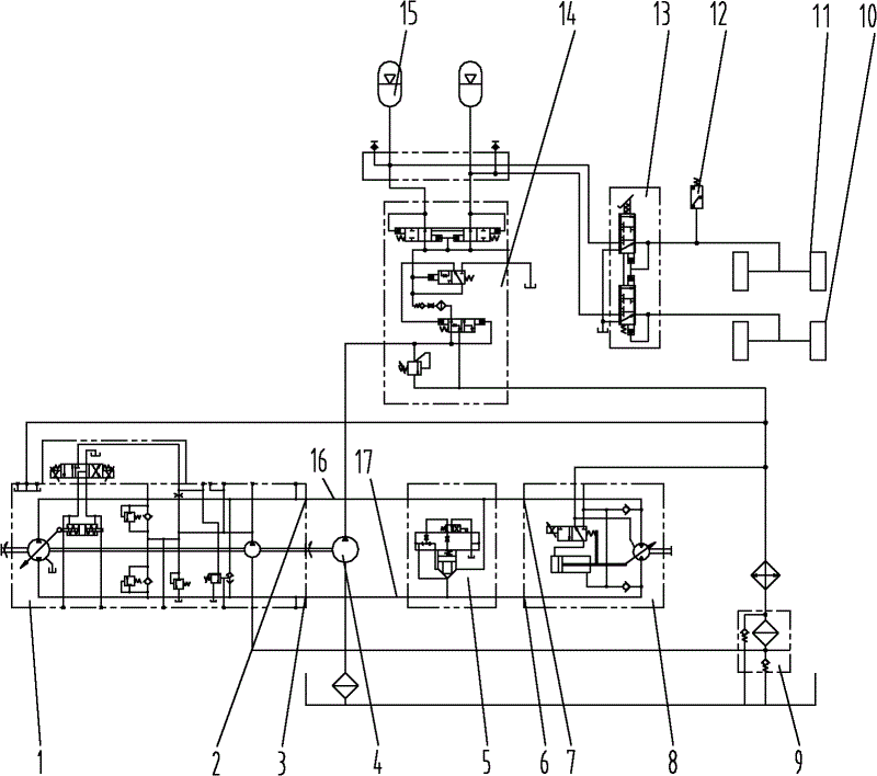
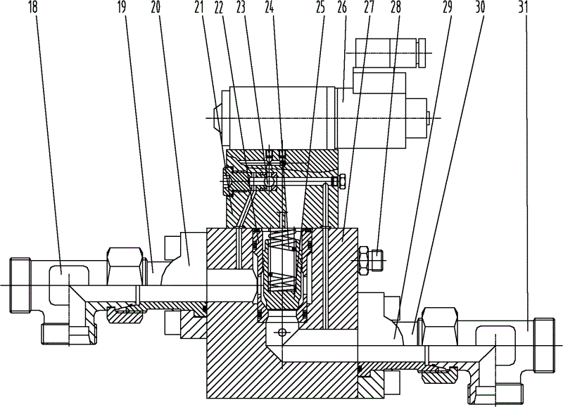
[0012] Refer to attached figure 1 , figure 2 : snow blower hydraulic travel differential mechanism, including travel hydraulic system, brake hydraulic system; described travel hydraulic system includes electric proportional variable pump 1 and electric proportional variable motor 8; oil port A 2 of electric proportional variable pump 1, Oil port B 3 is connected to oil port AA 7 and oil port BB 6 corresponding to the electric proportional variable motor 8, wherein the connecting pipeline between oil port A 2 and oil port AA 7 is oil line A 16, and oil port B 3 is connected to oil port The connecting pipeline of BB 6 is oil circuit B 17; the brake hydraulic system includes a hydraulic pump 4, a filling valve 14, a pedal brake valve 1...


PUM


Abstract

A hydraulic traveling differential mechanism of a snow blower comprises a traveling hydraulic system and a braking hydraulic system. The traveling hydraulic system comprises an electric proportion variable pump and an electric proportion variable motor, and an oil port A and an oil port B of the electric proportion variable pump are respectively connected with a corresponding oil port AA and a corresponding oil port BB of the electric proportion variable motor. The hydraulic traveling differential mechanism is characterized by further comprising a differential control valve and a pressure relay, wherein one end of the differential control valve is communicated with an oil path A through a three-way connector A, and the other end of the differential control valve is communicated with an oil path B through a three-way connector B. The pressure relay is connected into a hydraulic pipeline between a pedal braking valve and a front axle brake or a rear axle brake, and a signal line of the pressure relay is connected with a solenoid directional valve on the differential control valve.

Description

technical field [0001] The invention belongs to the field of hydraulic systems, in particular to a hydraulic traveling differential mechanism of a snow blower. Background technique [0002] The large and medium-sized snow blower (helical rotor type) is mainly composed of an engine, a transmission device, a snow throwing device and a car body. The transmission device includes travel hydraulic system, steering hydraulic system, working device hydraulic system and brake hydraulic system. The engine drives the hydraulic pump to provide hydraulic energy to the walking hydraulic system, steering hydraulic system, working device hydraulic system and brake hydraulic system. The hydraulic actuators convert the hydraulic energy into mechanical energy to realize the snow blower's walking, steering, and snow throwing functions. [0003] The hydraulic walking system of the snow blower consists of a hydraulic pump, a hydraulic motor, a two-speed gearbox, and front and rear drive axles. ...

Claims


Application Information

Patent Timeline
Patent Type & Authority Applications(China)
IPC IPC(8): B60K17/10B60T11/18B60T15/36F15B11/04
Inventor 张嘉琦
Owner TIANJIN CHENGPU ENG MACHINERY
Learn More