Connecting joint of steel pipe concrete column and profile steel concrete beam

A technology for concrete-filled steel tubular columns and concrete beams, which is applied in construction and building construction, etc., can solve problems such as long construction period, inability to construct, and steel bars collide, and achieve simple construction, increase in total material costs, and increase in the cost of peripheral steel pipes. Effect

Active Publication Date: 2012-08-01
CHINA NERIN ENG
View PDF5 Cites 8 Cited by
  • Summary
  • Abstract
  • Description
  • Claims
  • Application Information

AI Technical Summary

Problems solved by technology

The construction unit of this kind of joint form must open holes for the steel pipes to pass through the steel bars in the processing plant or on site. The opening of the steel pipe caused damage to the column section, and the construction period was long

Method used


Image

  • Connecting joint of steel pipe concrete column and profile steel concrete beam
  • Connecting joint of steel pipe concrete column and profile steel concrete beam
  • Connecting joint of steel pipe concrete column and profile steel concrete beam

Examples


Embodiment approach

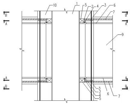
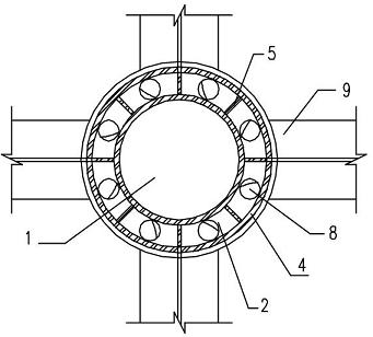
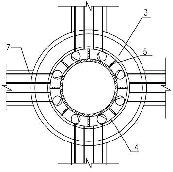
[0013] A connection node between a steel pipe concrete column and a steel concrete beam. A pair of large and small ring plates 3 and 2 with different diameters are arranged at the intersection of the inner steel pipe 1 of the steel pipe concrete column 10 and the steel beam flange 6 in the steel concrete beam 9. The two ring plates 2 and 3 are horizontally and vertically staggered. In order to avoid damage to the section of the steel concrete column 10 caused by opening a large number of steel holes on the steel pipe 1 in the steel pipe concrete column 10, the small ring plate 2 and the steel The steel beam flange 6 in the concrete beam 9 is welded, the large ring plate 3 is welded with the beam internal longitudinal reinforcement 7 in the steel concrete beam 9, and a steel pipe 4 is arranged between the ring plates 2 and 3 to connect the large and small ring plates 3 , 2 welded together as a whole, for further reinforcement, the steel pipe 1 in the column of the concrete-fille...


PUM


Abstract

The invention discloses a connecting joint of a steel pipe concrete column and a profile steel concrete beam. The intersection between a steel pipe in the steel pipe concrete column and a flange girth of the profile steel concrete beam is provided with a pair of large and small annular plates of different diameters; the horizontal and vertical positions of the two annular plates are staggered away from each other; the small annular plate is welded with a steel beam flange girth in the profile steel concrete beam; the large annular plate is welded with a longitudinal bar in the profile steel concrete beam; a steel pipe is arranged between the annular plates for welding the large and small annular plates into a whole; and the steel pipe of the steel pipe concrete column and the steel pipe for connecting the two annular plates are connected into a whole through a vertical rib. The connecting joint of the steel pipe concrete column and the profile steel concrete beam disclosed by the invention has the advantages that: 1, a large quantity of steel bar holes are not required to be formed on a steel pipe in a steel pipe concrete column; 2, damages to the section of a profile steel concrete column caused by steel pipe punching are avoided; and 3, convenience is brought to construction casting and compacting of concrete.

Description

[0001] technical field [0002] The invention relates to a building structure node form, in particular to a beam-column node in a steel-concrete composite structure. Background technique [0003] At present, the joint method between the steel concrete column (the inner steel pipe is steel pipe) and the steel concrete beam is as follows: the steel pipe in the steel pipe concrete column is provided with a ring plate at the upper flange of the steel beam, the flange of the steel beam in the steel beam is welded to the ring plate, and the steel bar in the steel beam Through section steel, partly bent around the steel pipe. The construction unit of this kind of joint form must open holes for the steel pipes to pass through the steel bars in the processing plant or on site. The opening of the steel pipe caused damage to the column section, and the construction period was long. Contents of the invention [0004] The purpose of the present invention is to provide a new type of c...

Claims


Application Information

Patent Timeline
Patent Type & Authority Applications(China)
IPC IPC(8): E04B1/58
Inventor 左菊林李大浪李涛
Owner CHINA NERIN ENG
Why Eureka
Try Eureka