Hole sealing method for gas drainage drill

A technology of gas drainage and composition, which is applied in the direction of gas discharge, earthwork drilling, sealing/package, etc., can solve the problems of reducing foaming ratio, increasing the amount of polyurethane material liquid, and short service life, so as to reduce the material Dosage, increase foaming ratio, improve the effect of mixing effect

Inactive Publication Date: 2012-08-01
BEIJING TIANHAI ZONGHENG TECH
View PDF1 Cites 7 Cited by
  • Summary
  • Abstract
  • Description
  • Claims
  • Application Information

AI Technical Summary

Problems solved by technology

[0006] In the actual operation of the above method, components A and B need to be mixed in advance, and the device needs to be cleaned after use, because the residual material liquid will react and foam in the device, blocking the pipeline and joints, and the service life of the device is short
The distribution of the feed liquid in the sealing area is to manually move the discharge pipe outwards slowly, and the distribution of the feed liquid is difficult to achieve uniformity
The material liquid is blown by compressed air, the material liquid will inevitably float in the air, and the polyurethane material liquid has a strong stimulating and damaging effect on the human respiratory tract before it fully reacts, which will cause harm to the personal health of the operator.
In addition, the foaming agent in the feed liquid will be taken away by a large amount of compressed air, thereby reducing the foaming ratio and increasing the amount of polyurethane feed liquid

Method used


Image

  • Hole sealing method for gas drainage drill

Examples


Embodiment 1

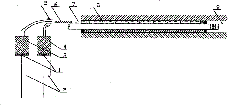
[0017] Two material cylinders with an inner diameter of 100mm are fixed side by side on the frame, and the tails of the piston rods are hard connected with connecting rods. Put the flexible packaging bag containing 1000ml of components A and B into the material tank, connect the discharge port to the five-way, and connect the compressed air to the five-way, one port of the five-way is connected to the mixing element, and the mixing element is connected to the The material liquid delivery pipe, the length of the feed liquid delivery pipe entering the inside of the gas borehole is 9500mm, and there is a discharge port with a diameter of 1.5mm every 1000mm on the pipe wall. Use compressed air to push the pistons of the two material cylinders to advance synchronously, inject the material, mix it with the compressed air in the bottom bracket, and then mix it into the material liquid in the mixing element. The material liquid flows out to the gas through the outlet on the wall of the...

Embodiment 2

[0019] With embodiment 1, in the middle of the material cylinder of two inner diameters 100mm that are discharged into side by side, increase the air cylinder of an inner diameter 40mm as additional power, the afterbody of 3 piston rods is hard-connected with connecting rod, and other is identical. The time required for injection is 50 seconds.

Embodiment 3

[0021] Same as in Example 1, the material tank in which component B is placed is replaced with a material tank with an inner diameter of 80mm, the dosages of components A and B are 1000ml and 640ml respectively, and the others are the same. The reaction ratio of A and B materials is 100:64 (volume ratio).


PUM


Abstract

Provided is a hole sealing method for a gas drainage drill. A hole sealing process is that two pistons capable of lifting synchronously are pushed by using compacted air, and two reacting components of components A and components B of polyurethane foam in two material vats are injected out simultaneously. The components A and the components B are first packaged through soft package bags, and the package bags are provided with discharging pipes respectively. The components A and the components B pass through the discharging pipes to a five-way member, and the five-way member is provided with two connectors to be connected with the compacted air. After the components A and the components B are mixed with the compacted air in the five-way member and mixed into material liquid through a mixing element connected with the five-way member, the material liquid jet-flows to a hole sealing area of the gas drainage drill from discharging ports distributed on a material conveying soft pipe wall, then reacts, and foams to seal an annular gap between the gas drainage drill and a drainage pipe.

Description

technical field [0001] The invention relates to a hole sealing method, in particular to a hole sealing method used for gas drainage drilling, and belongs to the field of coal mine safety. Background technique [0002] Gas control is the top priority of coal mine safety. An important part of gas control is the gas drainage before mining, and a key factor affecting gas drainage is the sealing quality of the borehole, that is, the drainage pipe and the borehole. Sealing of the annular gap between. Due to its good sealing effect and convenient use, two-component polyurethane hole sealing is widely used in the sealing of coal mine gas drainage holes. [0003] The early polyurethane sealing method is as disclosed in "Research on Polyurethane Sealing Can Improve Gas Drainage Effect" in the 8th issue of "Coal Engineering" in 2003: first prepare the required amount of linen and the iron wire for binding the linen. Weigh the required amount of components A and B according to the pro...

Claims


Application Information

Patent Timeline
Patent Type & Authority Applications(China)
IPC IPC(8): E21B33/13E21F7/00
Inventor 胡兴胜李响赖永忠
Owner BEIJING TIANHAI ZONGHENG TECH
Why Eureka
Try Eureka