
Blade and impeller of vertical shaft wind driven generator

A wind turbine, vertical shaft technology, applied in the field of blades and impellers, can solve the problems of aggravated friction and cutting action, large starting torque, and poor operation stability.

Inactive Publication Date: 2012-08-01
赵立华
View PDF7 Cites 1 Cited by
  • Summary
  • Abstract
  • Description
  • Claims
  • Application Information

AI Technical Summary

Problems solved by technology

However, this model also has the defects of large starting torque, difficulty in starting at low wind speed, and poor running stability.
The invention patent with the publication number CN1916397A proposes a winglet device for a vertical axis wind power generator to solve the above problems. The winglet device disclosed in this patent adopts a sheet-like structure, and the structure of the device is simple, which can relieve the wind to a certain extent when the impeller rotates. The problem of reduced wind energy utilization due to vortex airflow loss
However, the cross-section of the winglet device is a non-airfoil structure, and the air flow will not generate lift on the blade when it flows through the winglet device; the non-streamlined structural shape of the winglet device also intensifies the friction between the impeller and the air flow when it rotates and cutting action, which increases the operating noise of the wind turbine

Method used


Image

  • Blade and impeller of vertical shaft wind driven generator
  • Blade and impeller of vertical shaft wind driven generator
  • Blade and impeller of vertical shaft wind driven generator

Examples


Embodiment Construction

[0023] The blade and impeller of the vertical axis wind power generator of the present invention will be further described in detail below in conjunction with the accompanying drawings and specific embodiments.

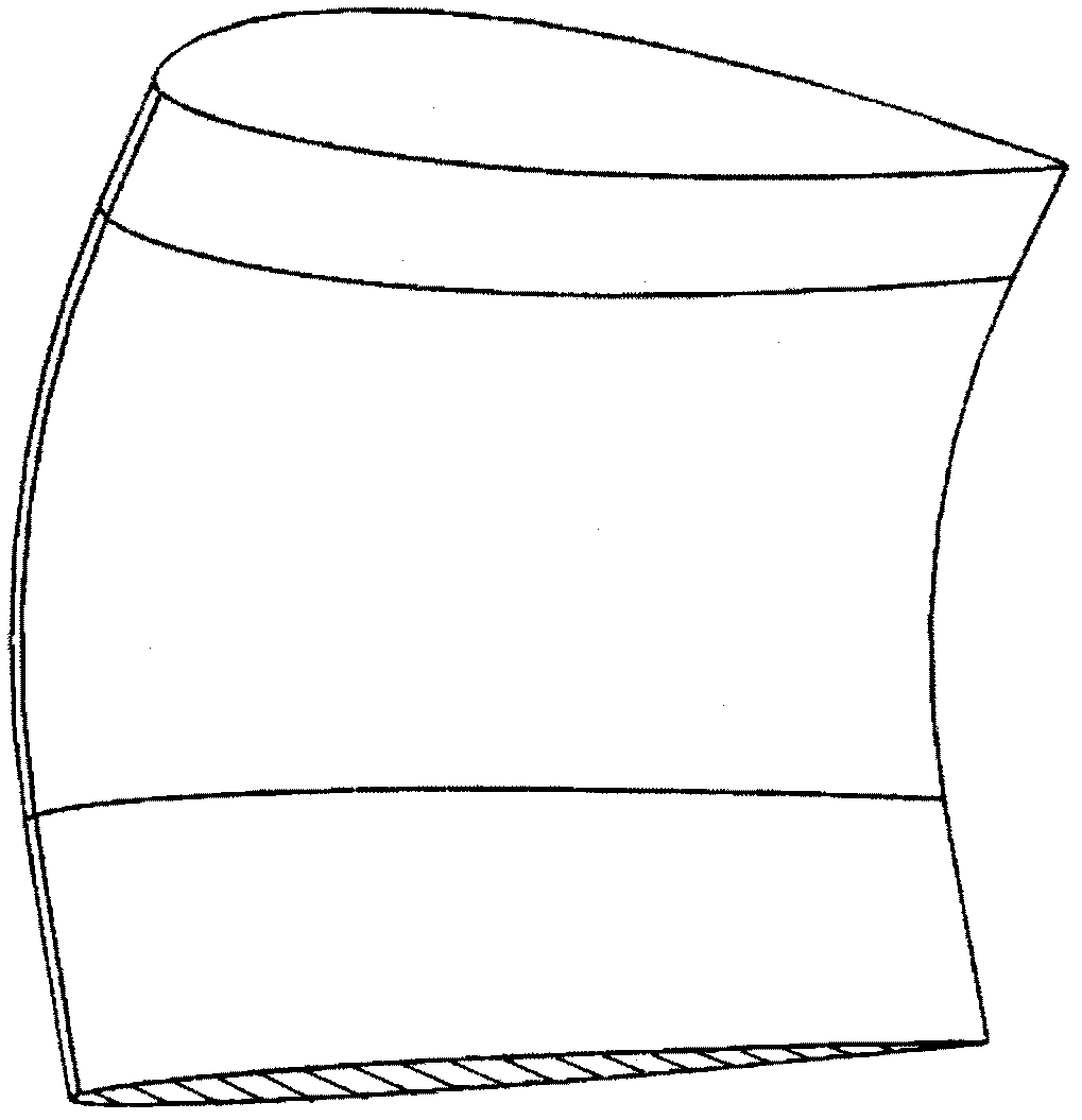
[0024] Such as Figure 4 Shown, the cross-section of the blade of the vertical axis wind power generator of the present invention is an airfoil, and the airfoil referred to in the present invention refers to the streamlined cross-section of the wing. The lift force is distributed in the shape of a bird's wing, and the lift force can provide power for the rotation of the impeller. The blade cross section of the present invention can be any airfoil shape. This embodiment adopts the symmetrical airfoil shape described by the following coordinates, (1.0000, 0.00158), (0.9500, 0.01008) , (0.9000, 0.01810), (0.8000, 0.03279), (0.7000, 0.04580), (0.6000, 0.05704), (0.5000, 0.06617), (0.4000, 0.07254), (0.3000, 0.07502), (0.2702), (0.2704) 0.2000, 0.07172), (0.1500, 0.06682...


PUM


Abstract

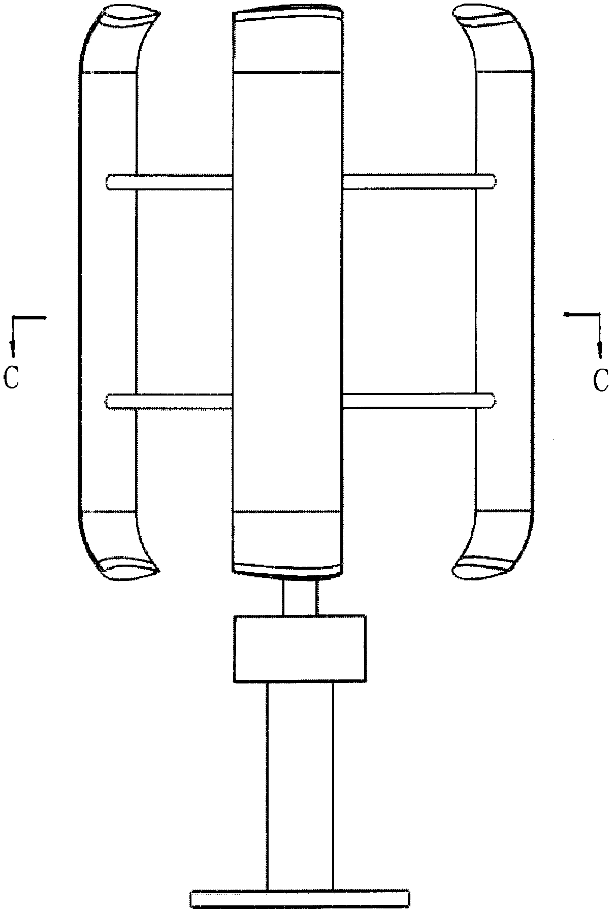
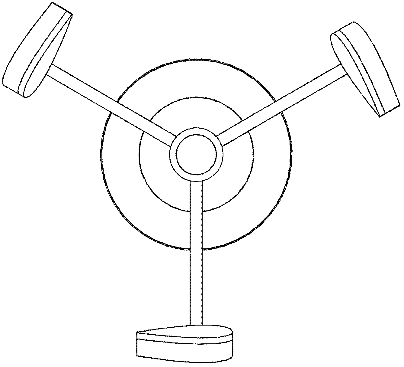
The invention relates to a vertical shaft wind driven generator, in particular to a blade and an impeller which are capable of improving the efficiency of the vertical shaft wind driven generator and running stably without noise. The blade of the vertical shaft wind driven generator consists of a main wing and auxiliary wings, wherein the cross section of the blade is wing-shaped, and the auxiliary wings are bent towards a wheel axle, are arranged in vertical symmetry and are connected with a main wing section to form the blade. According to the blade with a bent structure and the impeller consisting of the blade, when the blade rotates around the center line of the wheel axle, an auxiliary wing section can reduce the loss of swirling airflow of the blade, so that the efficiency of the wind driven generator is improved; the rotation moment of the blade can be increased, and low-wind-speed start and operation of the impeller are realized; and the bending stress of the blade can be reduced, the blade is lighter, the rotating speed of the blade is higher, and the operation stability of the impeller is enhanced. The blade has a streamline shape, so intense friction and cutting with the airflow are avoided, and the noise of the wind driven generator can be eliminated.

Description

technical field [0001] The invention relates to a vertical-axis wind-driven generator, in particular to a blade and an impeller of a vertical-axis wind-driven generator capable of starting in a breeze, stable in operation and noiseless. Background technique [0002] Wind turbines can be divided into horizontal axis wind turbines and vertical axis wind turbines. Studies have shown that compared with horizontal axis wind turbines, vertical axis wind turbines have the following advantages: simple structure, high utilization rate of wind energy, convenient installation and maintenance, and low noise. However, this model also has the defects of large starting torque, difficulty in starting at low wind speed, and poor running stability. The invention patent with the publication number CN1916397A proposes a winglet device for a vertical axis wind power generator to solve the above problems. The winglet device disclosed in this patent adopts a sheet-like structure, and the structur...

Claims


Application Information

Patent Timeline
IPC IPC(8): F03D9/00F03D3/06
CPCY02E10/74
Inventor 赵立华赵建华林荫柳明
Owner 赵立华
Learn More