Rotary compressor and manufacturing method thereof

A rotary compressor, rotary compression technology, applied in rotary piston/swing piston pump components, mechanical equipment, machines/engines, etc., to achieve the effect of improving the efficiency of assembly operations

Active Publication Date: 2012-08-01
SANYO ELECTRIC CO LTD
View PDF12 Cites 3 Cited by
  • Summary
  • Abstract
  • Description
  • Claims
  • Application Information

AI Technical Summary

Problems solved by technology

That is, it is necessary to reduce the outer diameter of the eccentric part, but at present, the assembly method of inserting the roller into the eccentric part from the end after machining the rotating shaft is used, so the outer diameter of the eccentric part (the inner diameter of the roller) cannot be made closer to or smaller than the rotating shaft. Shaft outer diameter

Method used


Image

  • Rotary compressor and manufacturing method thereof
  • Rotary compressor and manufacturing method thereof
  • Rotary compressor and manufacturing method thereof

Examples


Embodiment 1

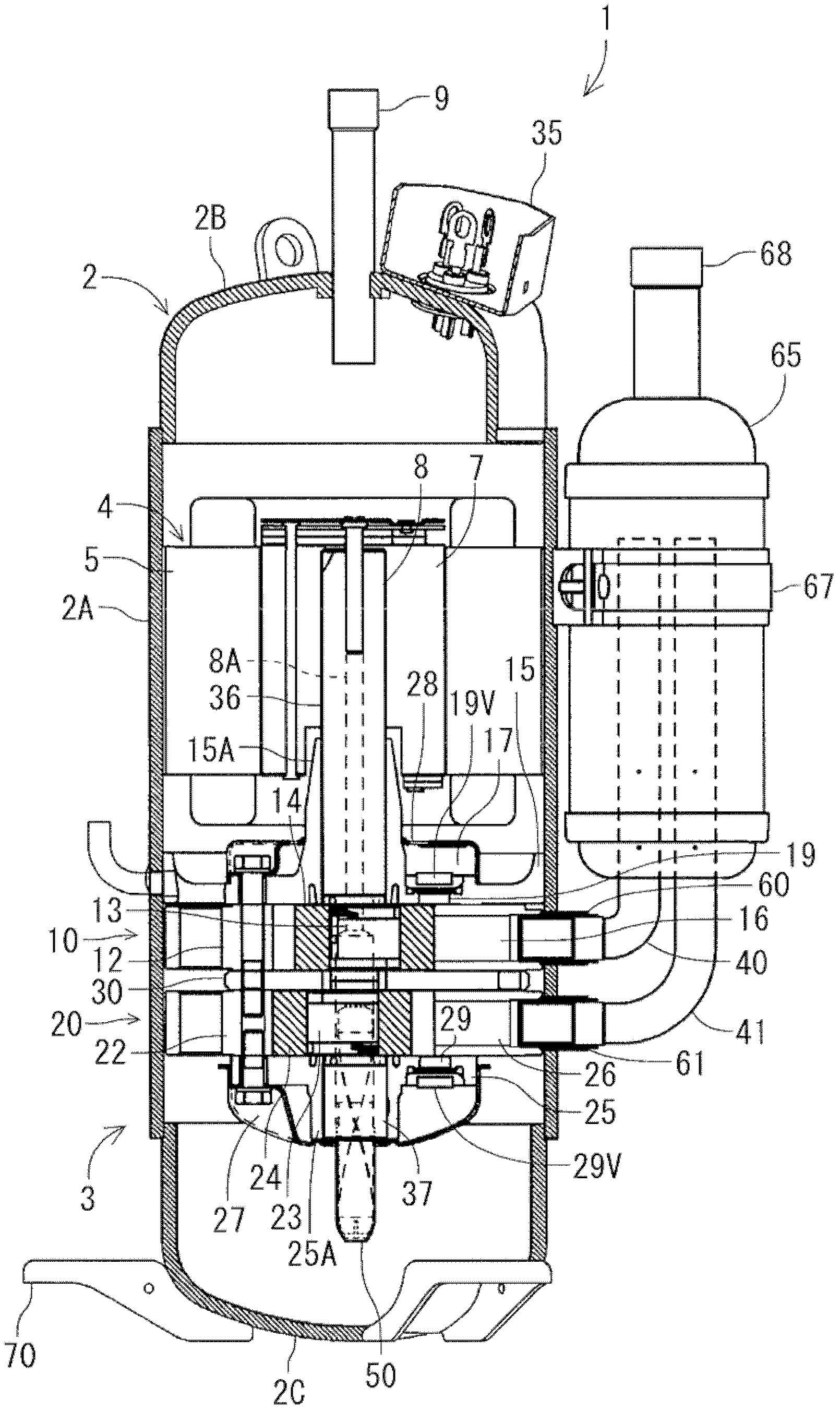
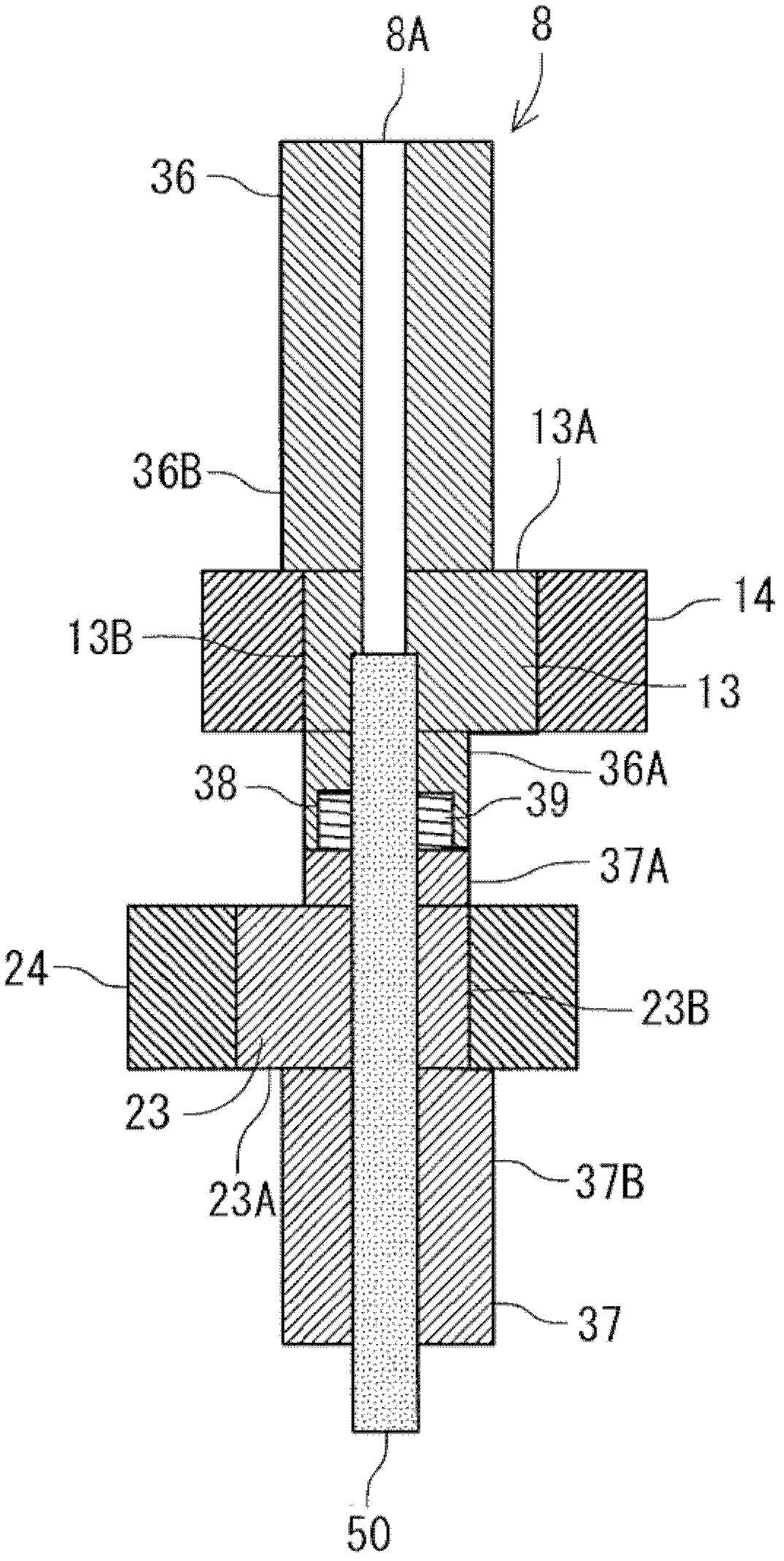
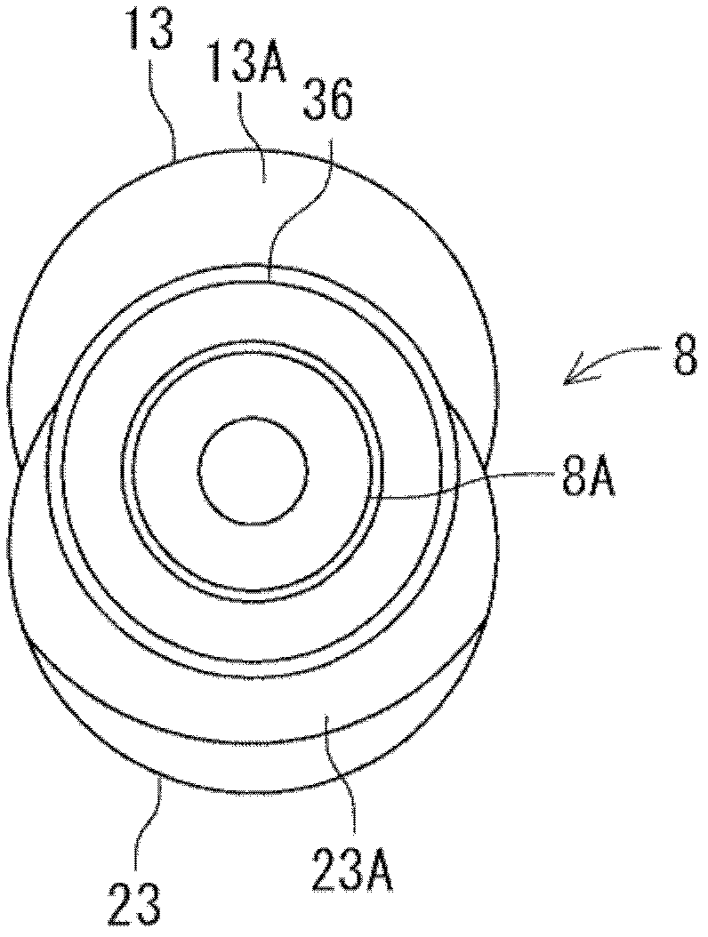
[0051] figure 1 It is a longitudinal sectional side view of the rotary compressor 1 to which the first embodiment of the present invention is applied, figure 2 Is an enlarged longitudinal sectional side view of the main part of the rotating shaft 8, image 3 It is a bottom view of the rotating shaft 8. The rotary compressor in the embodiment is an internal high-pressure type two-cylinder hermetic rotary compressor provided with first and second rotary compression units.

[0052] The rotary compressor 1 houses a rotary compression mechanism 3 composed of first and second rotary compression units 10 and 20 in the lower part of the internal space of a vertical cylindrical airtight container 2 made of steel plate. A drive unit 4 composed of an electric motor is housed above the compression mechanism 3.

[0053] The airtight container 2 is composed of a container body 2A housing the drive unit 4, the first and second rotary compression units 10, 20 (the rotary compression mechanism par...

Embodiment 2

[0080] then, Figure 4 and Figure 5 Show other embodiments of the present invention, the figures are used with Figure 1 to Figure 3 Components denoted by the same reference numerals have the same functions. In this embodiment, the connecting portions 36A, 37A of the rotating shaft portions 36, 37 are not formed with thread grooves. Instead, a plurality of concave portions 36C, 37C and convex portions 36D, 37D are formed. Furthermore, the concave portion 36C of the first rotating shaft portion 36 corresponds to the convex portion 37D of the second rotating shaft portion 37, and the convex portion 36D of the first rotating shaft portion 36 corresponds to the concave portion 37C of the second rotating shaft portion 37.

[0081] When the two rotating shaft portions 36 and 37 are connected, the concave portion 36C of the first rotating shaft portion 36 engages with the convex portion 37D of the second rotating shaft portion 37, and the convex portion 36D of the first rotating shaft ...


PUM


Abstract

The invention provides a rotary compressor and a manufacturing method thereof, which reduce the slide loss between a roller and an eccentric portion as much as possible and cause no obstruction to the assembling operation. A rotating shaft (8) is composed of a first rotating shaft portion (36) which is supported by an upper bearing and has a first eccentric portion (13), and a second rotating shaft portion (37) which is connected with the first rotating shaft portion, is supported by a lower bearing and has a second eccentric portion (23). The portion of each eccentric portion opposite to the projecting portion of the projecting eccentric portion of each rotating shaft portion is located at the inner side, with respect to partial rotating shaft portions supported by the bearings.

Description

Technical field [0001] The present invention relates to a rotary compressor and a method of manufacturing the same. The compressor houses a drive unit and a rotary compression unit driven by a rotating shaft of the drive unit in a closed container. Background technique [0002] At present, this type of rotary compressor is composed of a rotary compression unit housed in a lower part of a closed container and a drive unit (motor) housed in an upper part thereof. The drive unit is composed of a stator and a rotor. The stator is installed in a ring shape along the inner peripheral surface of the upper space of the airtight container. The rotor is rotatably interpolated by the magnetic field generated by the stator and fixed to the rotation of the crankshaft that also drives the rotary compression unit. Shaft. [0003] The rotary compression unit is composed of an air cylinder, a roller that is fitted to an eccentric portion formed on the rotating shaft and rotates eccentrically in th...

Claims


Application Information

Patent Timeline
Patent Type & Authority Applications(China)
IPC IPC(8): F04C29/00
Inventor 小笠原弘丞椎根广大小暮吉久
Owner SANYO ELECTRIC CO LTD
Why Eureka
Try Eureka