Low-cost phased array antenna based on cross coupling control

A phased array antenna, low-cost technology, applied in wireless communication technology, radar field, to achieve the effect of cost reduction

Inactive Publication Date: 2012-08-01
UNIV OF ELECTRONIC SCI & TECH OF CHINA
View PDF3 Cites 20 Cited by
  • Summary
  • Abstract
  • Description
  • Claims
  • Application Information

AI Technical Summary

Problems solved by technology

[0007] The purpose of the present invention is to solve the

Method used


Image

  • Low-cost phased array antenna based on cross coupling control
  • Low-cost phased array antenna based on cross coupling control
  • Low-cost phased array antenna based on cross coupling control

Examples


Embodiment Construction

[0040] The technical solution of the present invention will be described in detail below with reference to the accompanying drawings, using the microstrip antenna as an array element, but the protection scope of the present invention is not limited to the implementation examples.

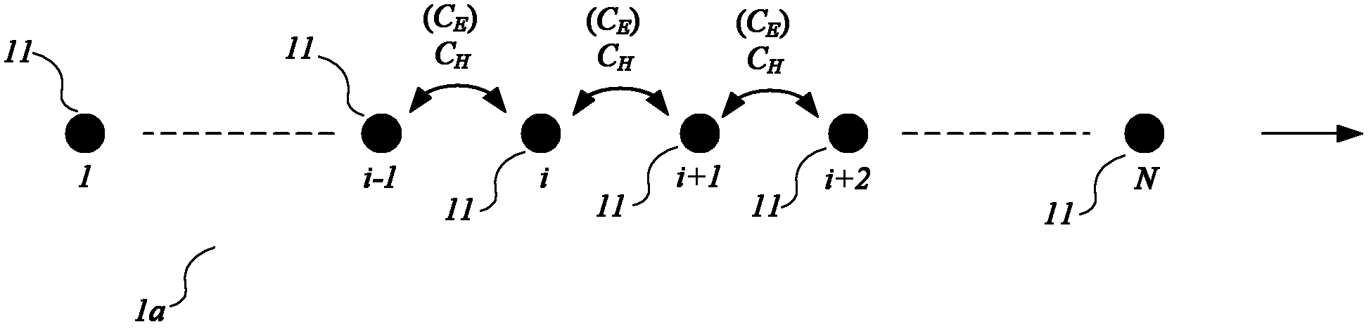
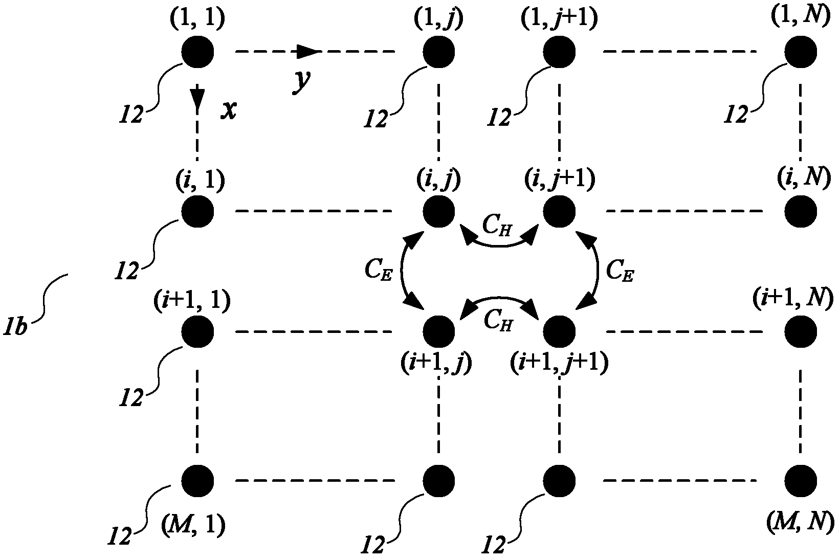
[0041] Fig. 1(a) describes the mutual coupling between array elements 11 in the linear antenna array 1a, and the mutual coupling between adjacent array elements is significantly higher than that of non-adjacent array elements. Similarly, Fig. 1 (b) has described the mutual coupling between array element 12 in the two-dimensional antenna array 1b, similarly adjacent array element mutual coupling will be significantly higher than non-adjacent array element or diagonal array element, so in the present invention Only the mutual coupling between adjacent array elements is considered. As an example, assuming that the one-dimensional linear array 1a shown in Figure 1(a) is an E-plane (or H-plane) array, th...


PUM


Abstract

The invention discloses a scheme of a novel phased array antenna which is low in cost and based on a cross coupling control technique among array elements and can reduce greatly overall cost and weight of phased array radars based on the fact the antenna array performance is not degraded. Some array elements in the scheme are connected to output ports of a feed network to perform direct feed, and the others perform indirect feed through cross coupling which is can be controlled flexibly, so that a novel array structure which is sparse for the feed network and is dense for array caliber surface is formed. The innovation of the low-cost phased array antenna based on the cross coupling control is that the cross coupling among the array elements is utilized but not restrained to perform coupling excitation for dummies in an array, so that the novel phased array antenna with low cost and light weight is established. The established phased array antenna combines a plurality of advantages, a periodical sparse antenna array structure guarantees that the antenna array has light weight, the cost of the phased array antenna is reduced to about half of the cost of the existing phased arrays, and the low-cost phased array antenna based on the cross coupling control can be used for wireless communication and radar systems.

Description

technical field [0001] The invention belongs to the field of wireless communication technology and radar technology, and specifically relates to a low-cost, light-weight sparse periodic phased array antenna based on effective control of mutual coupling between array elements, which can be used in beam scanning systems such as phased array radars . Background technique [0002] As a key component of communication and radar systems, antenna arrays provide the possibility for high-efficiency radiation and reception of electromagnetic waves, that is, the conversion of electromagnetic signals from guided wave mode to radiation mode in free space, or vice versa. Due to the need for beam scanning, early antenna arrays were scanned mechanically, but the speed of beam scanning was very slow. At the same time, once the antenna array design was completed, the array beam was fixed and could not be flexibly controlled. The phased array antenna uses the independent control of the excitat...

Claims


Application Information

Patent Timeline
IPC IPC(8): H01Q21/00H01Q1/36H01Q3/26
Inventor 屈世伟杨仕文何德军夏明耀聂在平
Owner UNIV OF ELECTRONIC SCI & TECH OF CHINA
Why Eureka
Try Eureka