Buffering mechanism on output shaft of power output device and servo motor comprising same

A buffer mechanism and power output technology, applied in the field of servo motors, can solve problems such as gear damage of the reducer and failure of the servo motor to operate normally, and achieve the effects of eliminating inertial force, simple structure, and simple and convenient adjustment

Active Publication Date: 2012-08-01
ZHONGSHAN DAGU HI TECH ELECTRONICS
View PDF4 Cites 1 Cited by
  • Summary
  • Abstract
  • Description
  • Claims
  • Application Information

AI Technical Summary

Problems solved by technology

The rotation range of the output shaft of the servo motor is limited by the limit mechanism. When the servo motor is in the forward or reverse limit position, due to the inertia of the load object, the load connector has an inertia to the output shaft at the above limit position. The greater the mass of the load connector, the greater the inertial force. Due to the impact of the inertial force, the phenomenon of tooth sweeping of the reducer gear is very likely to occur, resulting in gear damage, which makes the servo motor unable to operate normally, especially on precision instruments.

Method used


Image

  • Buffering mechanism on output shaft of power output device and servo motor comprising same
  • Buffering mechanism on output shaft of power output device and servo motor comprising same
  • Buffering mechanism on output shaft of power output device and servo motor comprising same

Examples


Embodiment Construction

[0039] The present invention will be described in further detail below in conjunction with the accompanying drawings and specific embodiments.

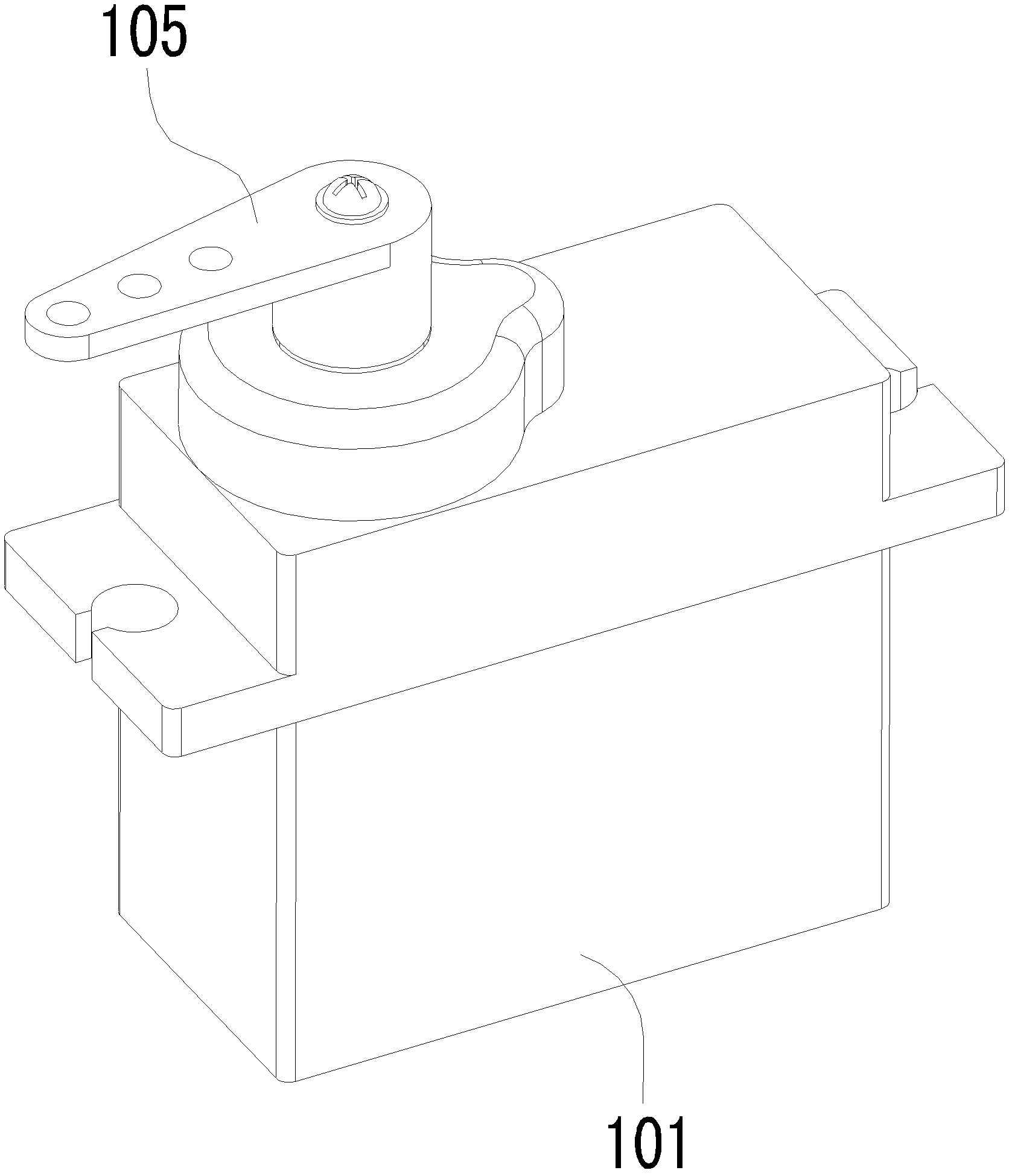
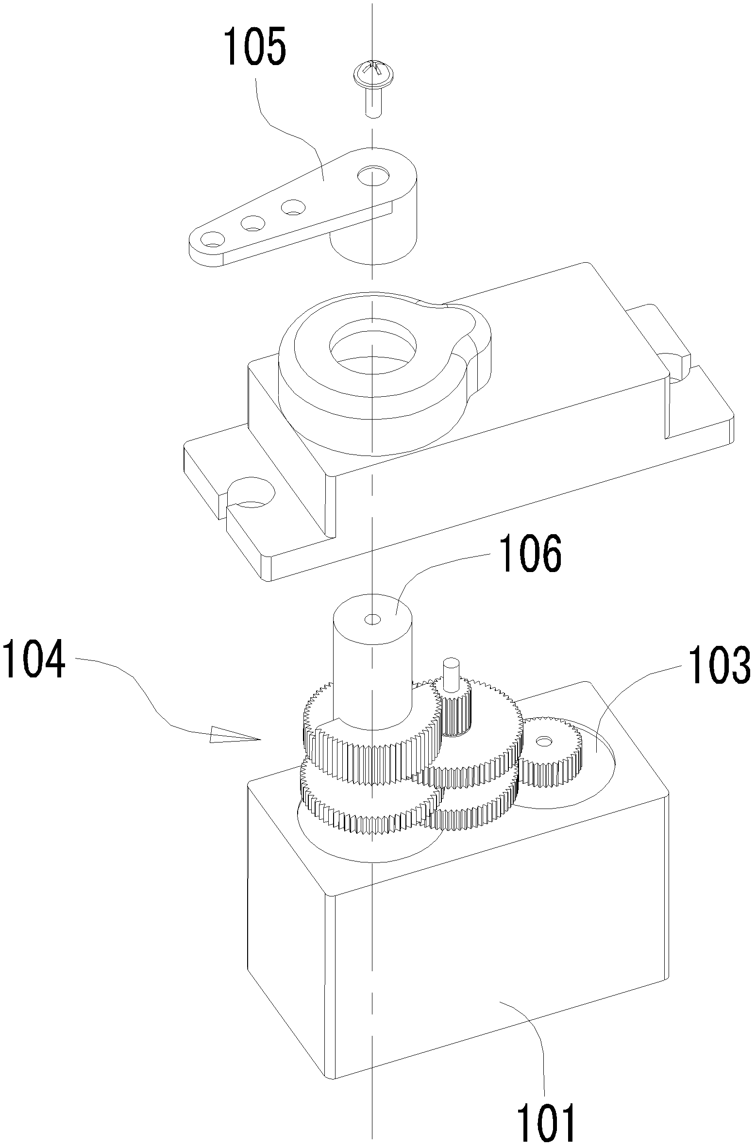
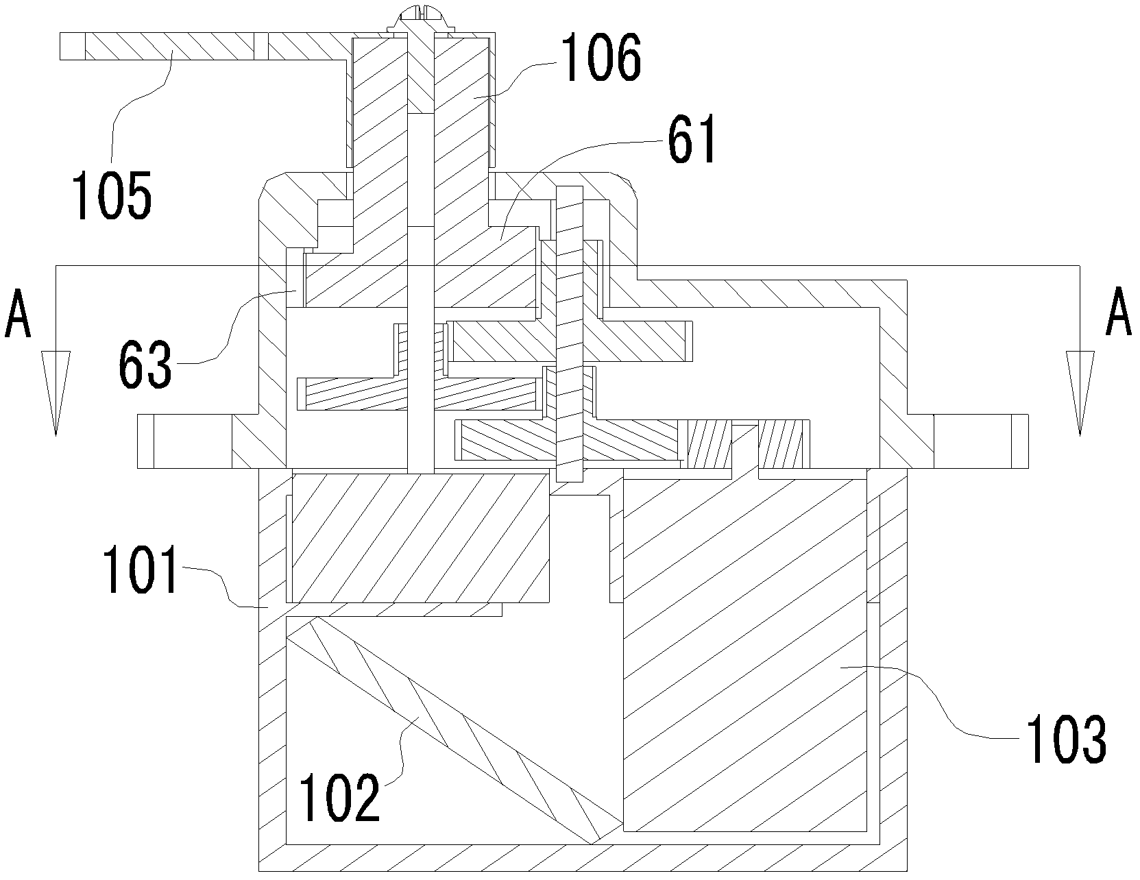
[0040] Such as Figure 5 to Figure 14 As shown, a buffer mechanism on the output shaft of a power output device, the buffer mechanism 1 is connected to a load connector (not shown in the figure), and the output shaft drives the buffer mechanism 1 to drive the load connector to move. The buffer mechanism 1 It includes the first layer of rotating parts 2 and the second layer of rotating parts 3 arranged in layers. The first layer of rotating parts 2 is fixedly installed on the output shaft 11. The second layer of rotating parts 3 is provided with a second pivot hole 31 through which a screw 32 penetrates. Screw the output shaft 11 through the second pivot hole 31 to rotatably install the second layer of rotating member 3 on the output shaft 11 and stack it on the top of the first layer of rotating member 2. The screw 32 and the second p...


PUM


Abstract

The invention relates to a buffering mechanism on an output shaft of a power output device and a servo motor comprising the same. The buffering mechanism is connected with a load connector and comprises a first rotation part and a second rotation part which are laminated, and the output shaft drives the buffering mechanism to drive the load connector to move. The first rotation part is fixedly mounted on the output shaft, the second rotation part is rotationally mounted on the output shaft, the second rotation part is connected with the load connector, the first rotation part is provided with one or multiple first magnets, the second rotation part is provided with second magnets, the second magnets and the first magnets correspond to each other in positions, and magnetic poles thereof are reversed and attracted each other. The buffering mechanism is applied on an output shaft of the servo motor. The buffering mechanism is simple in structure, capable of effectively eliminating inertia force of the load connector at two critical points of starting and stopping of the servo motor, and gears on a speed reduction mechanism are protected.

Description

technical field [0001] The invention relates to a buffer mechanism on an output shaft of a power output device and a servo motor applied thereto. Background technique [0002] In the prior art, servo motors are generally used as the power source on robots or model airplanes to drive the movement of various components. The structure of the servo motor is as follows: Figure 1 to Figure 4 As shown, it includes a casing 101, a control circuit 102, a motor 103, a speed reduction mechanism 104 and a swing arm 105, wherein the control circuit 102, the motor 103 and the speed reduction mechanism 104 are arranged in the casing, and the output shaft 106 of the speed reduction mechanism extends out of the casing and The swing arm 105 is rigidly connected, and the swing arm 105 is connected to a load connection (not shown in the figure). The rotation range of the output shaft of the servo motor is limited by the limit mechanism. When the servo motor is in the forward or reverse limit p...

Claims


Application Information

Patent Timeline
Patent Type & Authority Applications(China)
IPC IPC(8): H02K7/10H02N11/00
Inventor 赖荣杰
Owner ZHONGSHAN DAGU HI TECH ELECTRONICS
Why Eureka
Try Eureka