Magnetic suspension cylindrical linear movement guide rail pair

A technology of linear motion and magnetic suspension, applied in the field of guide rails, can solve the problems of unmentioned, waste of materials, unmentioned moving guide rail blocks, etc., and achieve the effect of easy processing and reasonable structure

Inactive Publication Date: 2012-08-08
NANTONG UNIVERSITY
View PDF11 Cites 4 Cited by
  • Summary
  • Abstract
  • Description
  • Claims
  • Application Information

AI Technical Summary

Problems solved by technology

[0014] (3) It is not mentioned that the distance between the moving guide rail blocks can be adjusted to meet the needs of installing workbenches of different lengths and sizes;
[0015] (4) It is not mentioned that each shaft (supporting guide rail) and two or more moving guide rail blocks installed on it form an independent functional part, and the distance between the two guide rail pairs can be adjusted to meet different installation requirements. Width Dimension Workbench Requirements
[0016] The guide rail pair is made into an independent functional part, and the shaft supports of the two shaft rods are installed on the same base. The size of the base changes according to the size of the machine bed, which wastes a lot of materials and cannot realize the modularization of the guide rail pair.
[0017] From the above analysis, it can be seen that there are no patents and literature reports on the magnetic levitation cylindrical linear motion guide rail pair in China at present.

Method used


Image

  • Magnetic suspension cylindrical linear movement guide rail pair
  • Magnetic suspension cylindrical linear movement guide rail pair
  • Magnetic suspension cylindrical linear movement guide rail pair

Examples


Embodiment

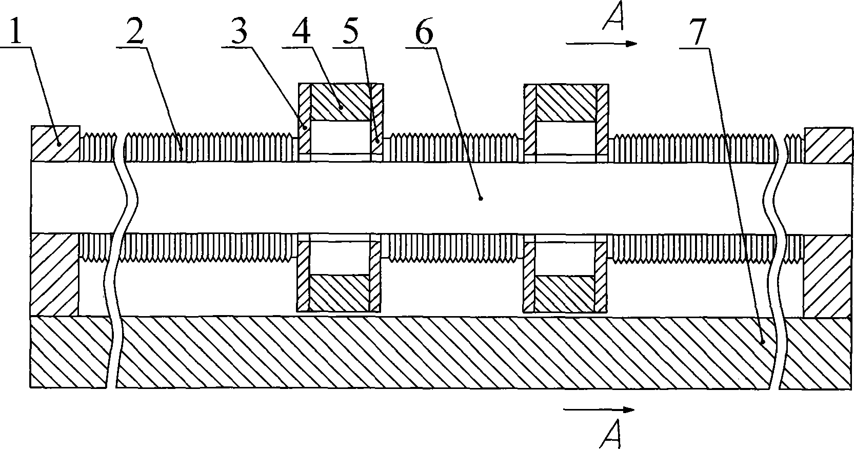
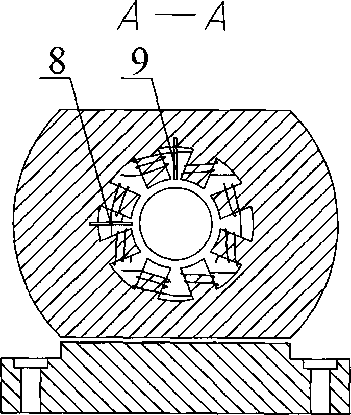
[0034] First, see attached figure 1 , 2 The magnetic levitation cylindrical linear motion guide rail pair includes a base 7, a support frame 1 installed at both ends of the base 7, a cylindrical support guide rail 6 installed on the support frame 1, and a magnetic levitation moving guide rail 4 set on the cylindrical support guide rail 6, The magnetic isolation plates 3 and 5 fixed at the two ends of the magnetic levitation guide rail 4, the organ type protective cover 2 which is set on the cylindrical support guide rail 6 and connected with the magnetic isolation plate 3 and the support frame 1, is installed at the level of the circumferential direction of the magnetic levitation guide rail 4 Displacement sensor 8 and vertical sensor 9.

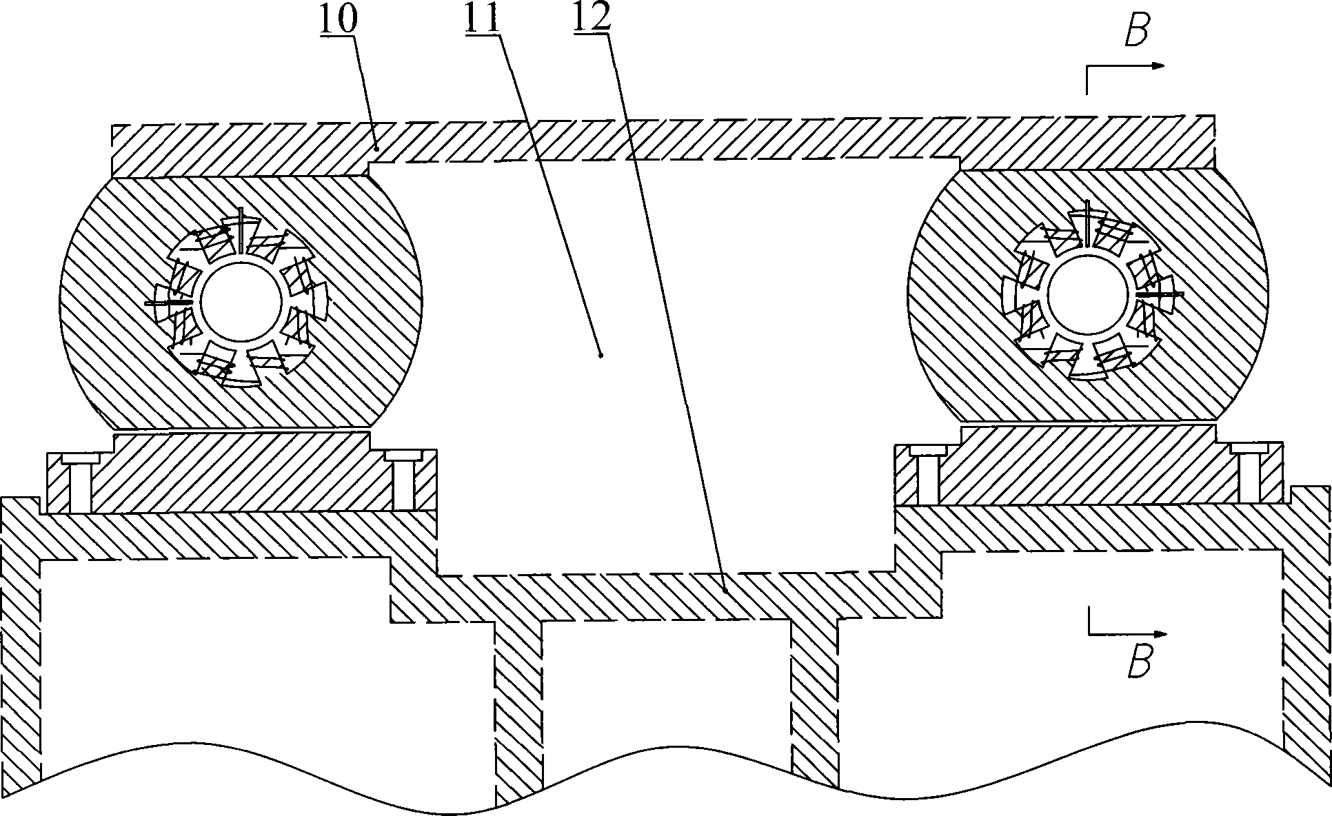
[0035] See attached image 3 , 4 , during practical application, the linear magnetic levitation cylindrical guide rails of the present invention are installed in pairs on the machine bed 12, the workbench 10 is installed on the magnetic l...


PUM


Abstract

The invention discloses a magnetic suspension cylindrical linear movement guide rail pair. The magnetic suspension cylindrical linear movement guide rail pair comprises supporting racks which are installed at the two ends of a pedestal, cylindrical supporting guide rails which are installed on the supporting racks, and magnetic suspension movable guide rails and magnetism isolating plates which are sleeved on the cylindrical supporting guide rails, and an organ-type shield, wherein the magnetism isolating plates are installed on the two sides of the magnetic suspension movable guide rails; displacement sensors are installed in the circumferential directions of the magnetism isolating plates; and a counter bore is formed on the pedestal and is used for installing the guide rail pair on a lathe body. The magnetic suspension cylindrical linear movement guide rail pair is reasonable in structure, integrates the advantages that the cylindrical guide rails are easy to process and magnetic suspension supports are free of contact and abrasion, high in speed, high in precision and are not required to be lubricated and sealed, can structurally decouple magnetic fields between a power source and the magnetic suspension guide rail pair and each magnetic support in the magnetic suspension guide rails easily, can serialize and modularize functional components of a lathe easily, and can meet a requirement for the performance of a linear feeding system of a high-speed and high-precision numerically-controlled lathe.

Description

technical field [0001] The invention relates to a precision machine tool and a guide rail pair for high-speed processing, in particular to an industrial application type magnetic levitation cylindrical linear motion guide rail pair. Background technique [0002] Modern manufacturing technology is developing in the direction of high speed, precision and modularization. The manufacturing industry has put forward higher and higher requirements for the performance of processing equipment. This demand has promoted the development of machine tool industry, especially CNC machine tools. However, the industrialization scale and product level of functional components supporting CNC machine tools are far from meeting the development requirements of CNC machine tools. The feed unit is an important functional part of the CNC machine tool. The final coordinates and contour accuracy of the processed workpiece are affected by the transmission accuracy, sensitivity and stability of the feed...

Claims


Application Information

Patent Timeline
Patent Type & Authority Applications(China)
IPC IPC(8): B23Q1/01H02N15/00
Inventor 廖萍马苏扬周一丹吴国庆倪红军黄明宇朱昱茅靖峰姜安栋夏正鹏
Owner NANTONG UNIVERSITY
Why Eureka
Try Eureka