Substation area back-up protecting method based on current differential principle

A technology of backup protection and current differential, which is applied in the direction of emergency protection circuit devices, electrical components, etc., to achieve the effect of shortening the operating time

Inactive Publication Date: 2012-08-08
INTEGRATED ELECTRONICS SYST LAB
View PDF2 Cites 23 Cited by
  • Summary
  • Abstract
  • Description
  • Claims
  • Application Information

AI Technical Summary

Problems solved by technology

Information sharing provides richer technical means for researching new principles and methods of relay protection. However, this feature has not been fully utilized by relay protection. It can be pr...

Method used


Image

  • Substation area back-up protecting method based on current differential principle
  • Substation area back-up protecting method based on current differential principle
  • Substation area back-up protecting method based on current differential principle

Examples


Embodiment 1

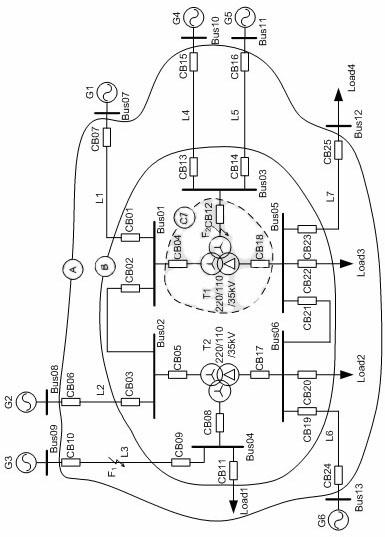
[0031] Embodiment 1 Taking the working condition of line L3 fault and the main protection refusing to operate as an example, the implementation process of the present invention is described:

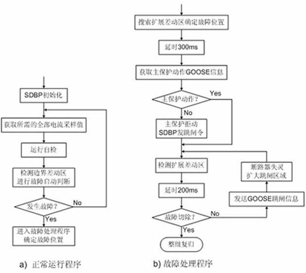
[0032] f 1 A fault occurs at the boundary differential zone A, and a differential current is detected, which is determined to be a fault state and enters the fault handling program. After the calculation of the current differential criterion, it is detected that the boundary differential zone A is in the differential criterion action state and the substation differential zone B is in the differential criterion braking state, so it is judged that the fault occurs in the outgoing line of the substation rather than Substation internal components. After it is determined as an outgoing line fault, enter the extended differential zone traversal program of the outgoing line fault, and remove the outgoing lines L1 and L2 from the boundary differential area A in sequence. At L3, expand the diff...

Embodiment 2

[0033] Embodiment 2 Taking the internal failure of transformer T1 and the refusal of circuit breaker CB12 as an example, the specific process is described:

[0034] f 2 A fault occurs at the boundary differential zone A, and a differential current is detected, which is determined to be a fault state and enters the fault handling program. After the calculation of the current differential criterion, it is detected that the boundary differential zone A and the substation differential zone B are both in the action state of the differential criterion, and it is determined that the faulty component is located inside the substation. Enter the extended differential area traversal program for component faults in the station, and remove the component differential area C from the differential area B in the station in sequence i (i.e. busbars Bus01, Bus02, Bus03, Bus04, Bus05, Bus06 and transformer T2), the extended differential zone formed in this process is in the action state of the d...


PUM


Abstract

The invention belongs to the filed of power system relay protection, in particular to a substation area back-up protecting method which is based on a current differential principle and applicable to an intelligent transformer substation. According to the method, information such as analog quantity, switching value and the like is acquired on the basis of high-speed communication networks and inter-station data channels inside the intelligent transformer substation, back-up protecting areas are processed in areas, all faults inside the transformer substation and on outgoing lines are positioned rapidly, reliably and accurately through the current differential principle, and under the condition of failure of a main protection and a breaker, a back-up tripping instruction is issued to isolate fault elements. The method changes the state of the prior art that selectivity of traditional back-up protection is achieved through fit of fault electric quantity and time limit step, simplifies configuration and setting of the back-up protection and shortens movement time limit of the back-up protection.

Description

technical field [0001] The invention belongs to the field of electric power system relay protection, and in particular relates to a station domain backup protection method based on the current differential principle suitable for intelligent substations. Background technique [0002] The purpose of the application of power system relay protection technology is to automatically and quickly remove the faulty equipment when the power grid fails, and to limit the scope of the fault to the smallest area, so as to ensure the normal operation of the fault-free part of the power grid. The basic principles of fault isolation include fast performance, selectivity, sensitivity, and reliability. According to the protection range and action characteristics, power system relay protection can be divided into two types: main protection and backup protection: the main protection can respond to various faults of the protected equipment and remove the fault in the shortest possible time limit (...

Claims


Application Information

Patent Timeline
IPC IPC(8): H02H7/22
Inventor 刘益青高厚磊高伟聪滕兆宏
Owner INTEGRATED ELECTRONICS SYST LAB
Why Eureka
Try Eureka