Forging method of roller for crawler excavator

An excavator and crawler-type technology, which is applied in the forging field of crawler excavator rollers, can solve problems such as large deformation resistance, mold failure, wear, etc., and achieve the effect of avoiding deformation failure

Active Publication Date: 2014-10-08
SHANGHAI YUNLIANG ENTERPRISE DEV
View PDF6 Cites 0 Cited by
  • Summary
  • Abstract
  • Description
  • Claims
  • Application Information

AI Technical Summary

Problems solved by technology

[0003] image 3 It is a schematic diagram of the two halves of the roller forging that is integrally forged by the common die-fitting forging method. After simulating the forging process with a special simulation software, it is found that image 3 It is difficult to fill the C part fully, and the mold D of the two half-moulds will be subject to great deformation resistance during the forging process, so the wear will be very serious, and the two half-moulds will soon fail

Method used


Image

  • Forging method of roller for crawler excavator
  • Forging method of roller for crawler excavator
  • Forging method of roller for crawler excavator

Examples


Embodiment Construction

[0024] The scheme of the present invention will be further described below in conjunction with the accompanying drawings.

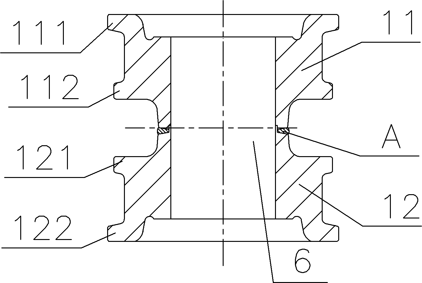
[0025] In the forging method of the roller for crawler excavator of the present invention, as Figure 7 As shown, the roller 1 includes two parts, the upper half 11 and the lower half 12, and the upper half 11 and the lower half 12 all have two flanges 111, 112, 121, 122. The roller forging method of the present invention , eliminating the welding process after forging separately, including the following steps:

[0026] 1) Heating the billet bar;

[0027] 2) if Figure 4 As shown, the upper half 11 of the roller is forged by the preliminary forging die 3 to obtain a semi-finished forging;

[0028] 3) Demoulding the semi-finished forgings;

[0029] 4) if Figure 6 As shown, the semi-finished forging is passed through the final forging die 4 to forge the lower half 12 of the roller to obtain the finished forging;

[0030] 5) Demoulding the finished fo...


PUM


Abstract

The invention provides a method for forging a roller for a crawler excavator. The method comprises the following steps of: firstly heating a blank bar; secondly forging the upper half part of the roller through an initial forging die; thirdly, forming the lower half part of the roller through a final forging die, namely forging the two parts of the roller respectively by means of two sleeved dies, wherein the forged rollers have the same central axis and do not need to be welded. Besides, the method is capable of ensuring full filling of a forge piece and also capable of effectively avoiding the deformation failure of the die.

Description

technical field [0001] The invention relates to a forging method of a roller used for a crawler excavator with a flange flange. Background technique [0002] The roller forging on a crawler excavator is a forging with a high shape complexity factor, such as figure 1 As shown, it includes two parts, an upper half 11 and a lower half 12, both of which have flanges 111, 112, 121, 122, and the traditional forging method is to separate the two parts are forged into figure 2 As shown in the shape, then machine the redundant part at B to form flange flanges 111, 112, 121, 122, and finally weld the machined two parts into a whole; as figure 1 As shown, during welding, the center hub 6 is installed, the two parts of the forgings 11, 12 are respectively processed into tongues that mesh with each other, and a chamfer for welding is left at the tongue position A, and finally welded. The disadvantage of the forging method is that the material consumption of the forging is large, the ...

Claims


Application Information

Patent Timeline
Patent Type & Authority Patents(China)
IPC IPC(8): B21K1/28
Inventor 陆友荣
Owner SHANGHAI YUNLIANG ENTERPRISE DEV
Why Eureka
Try Eureka