Vehicle tail gas purifying device

A technology for exhaust gas purification devices and vehicles, which is applied in the direction of charging system, electrical control, exhaust gas recirculation, etc., and can solve the problems of restricting the promotion and popularization of exhaust gas purification control devices, limited data, and low conversion efficiency

Pending Publication Date: 2017-09-05
雄创(上海)新能源科技有限公司
View PDF2 Cites 0 Cited by
  • Summary
  • Abstract
  • Description
  • Claims
  • Application Information

AI Technical Summary

Problems solved by technology

In the past, vehicles generally installed a three-way catalytic converter on the vehicle exhaust pipe to reduce the emission of harmful gases from the vehicle, but the three-way catalytic converter has the disadvantages of easy aging and low conversion efficiency
In the prior art, there are exhaust gas recirculation methods to reduce harmful gas emissions, for example: the invention patent published by the State Intellectual Property Office: a vehicle exhaust gas purification composite electronic control device, 2011100531134, specifically through the air injection electronic control subsystem and the engine exhaust gas recirculation EGR electronic control subsystem to reduce NOx emissions, but the input terminals of the two electronic control units in this technical solution are only the engine speed signal and the throttle position signal, that is, the input terminal of the first electronic contro

Method used


Image

  • Vehicle tail gas purifying device
  • Vehicle tail gas purifying device
  • Vehicle tail gas purifying device

Examples


Embodiment Construction

[0017] The present invention will be further described below in conjunction with the accompanying drawings and specific embodiments.

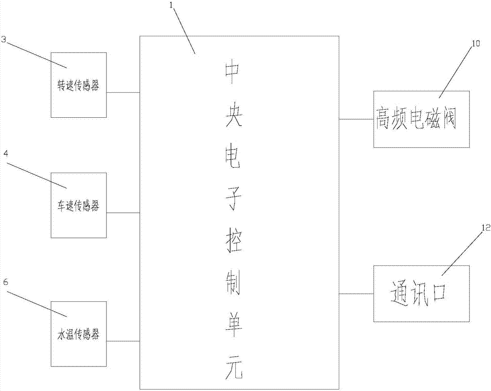
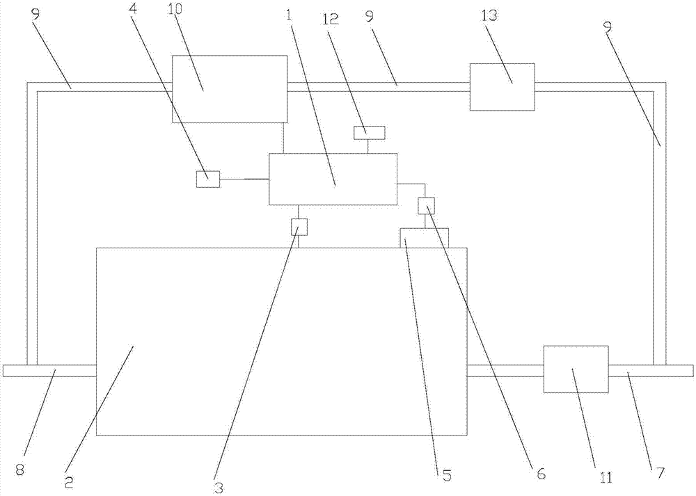
[0018] As shown in the figure, it includes a central electronic control unit (ECU) 1, a speed sensor 3 for measuring the speed of the crankshaft on the engine 2, a vehicle speed sensor 4 for measuring the speed of the car tires, and a water temperature sensor for the temperature of the water tank 5 on the engine 2 6 and the engine exhaust gas recirculation EGR electronic control system; the speed sensor 3 is connected to the input end of (ECU) 1 through a signal, the vehicle speed sensor 4 is connected to the input end of (ECU) 1 through a signal, and the water temperature sensor 6 is connected to the input end of (ECU) 1 through a signal Signal connection, the engine exhaust gas recirculation EGR electronic control system includes a bypass pipeline 9 for connecting the exhaust pipe 7 on the engine 2 and the intake pipe 8 on the engine 2. The c...


PUM


Abstract

The invention discloses a vehicle tail gas purifying device. The device comprises a central electronic control unit ECU (1), a rotating speed sensor (3), a vehicle speed sensor (4), a water temperature sensor (6), and an engine waste gas recirculation EGR electric control system; the rotating speed sensor (3) is connected with an input end of the ECU (1) through a signal; the vehicle speed sensor (4) and the input end of the ECU (1) are connected through a signal; the water temperature sensor (6) and the input end of the ECU (1) are connected through a signal; the engine waste gas recirculation EGR electric control system comprises a bypass pipeline (9); a high-frequency electromagnetic valve (10) is arranged in the bypass pipe (9); and a control end of the high-frequency electromagnetic valve (10) is connected with an output end of the ECU (1) through a signal. The vehicle tail gas purifying device can reduce the NOx emission more effectively, and further widens the application range.

Description

technical field [0001] The invention belongs to the technical field of automobile tail gas emission purification, and relates to a vehicle tail gas purification device. Background technique [0002] At present, the problem of vehicle exhaust emissions is already one of the sources of air pollution, and developed countries such as Europe and the United States have become more and more strict on exhaust emission indicators. In the past, vehicles generally installed a three-way catalytic converter on the vehicle exhaust pipe to reduce the emission of harmful gases from the vehicle, but the three-way catalytic converter has the disadvantages of easy aging and low conversion efficiency. In the prior art, there are exhaust gas recirculation methods to reduce harmful gas emissions, for example: the invention patent published by the State Intellectual Property Office: a vehicle exhaust gas purification composite electronic control device, 2011100531134, specifically through the air ...

Claims


Application Information

Patent Timeline
IPC IPC(8): F02D41/00F02M26/14
CPCF02D41/0077F02D2200/501F02D2200/101F02D2250/36F02D2200/02
Inventor 张启明
Owner 雄创(上海)新能源科技有限公司
Why Eureka
Try Eureka