Crankshaft oil wiper of internal combustion engine

A technology of oil scraper and internal combustion engine, applied in the direction of machines/engines, mechanical equipment, engine components, etc., can solve the problem of high exhaust gas pressure in the crankcase, achieve the effects of reducing exhaust gas pressure, simple process, and novel structure

Inactive Publication Date: 2012-08-15
NO 70 INST OF CHINA NORTH IND GRP
View PDF6 Cites 3 Cited by
  • Summary
  • Abstract
  • Description
  • Claims
  • Application Information

AI Technical Summary

Problems solved by technology

[0004] The present invention aims to solve the problem that the oil droplets are atomized when the crankshaft of the internal combustion engine rotates at high speed, resulting in a high pressure of the exhaust gas in the crankcase.

Method used


Image

  • Crankshaft oil wiper of internal combustion engine
  • Crankshaft oil wiper of internal combustion engine
  • Crankshaft oil wiper of internal combustion engine

Examples


Embodiment Construction

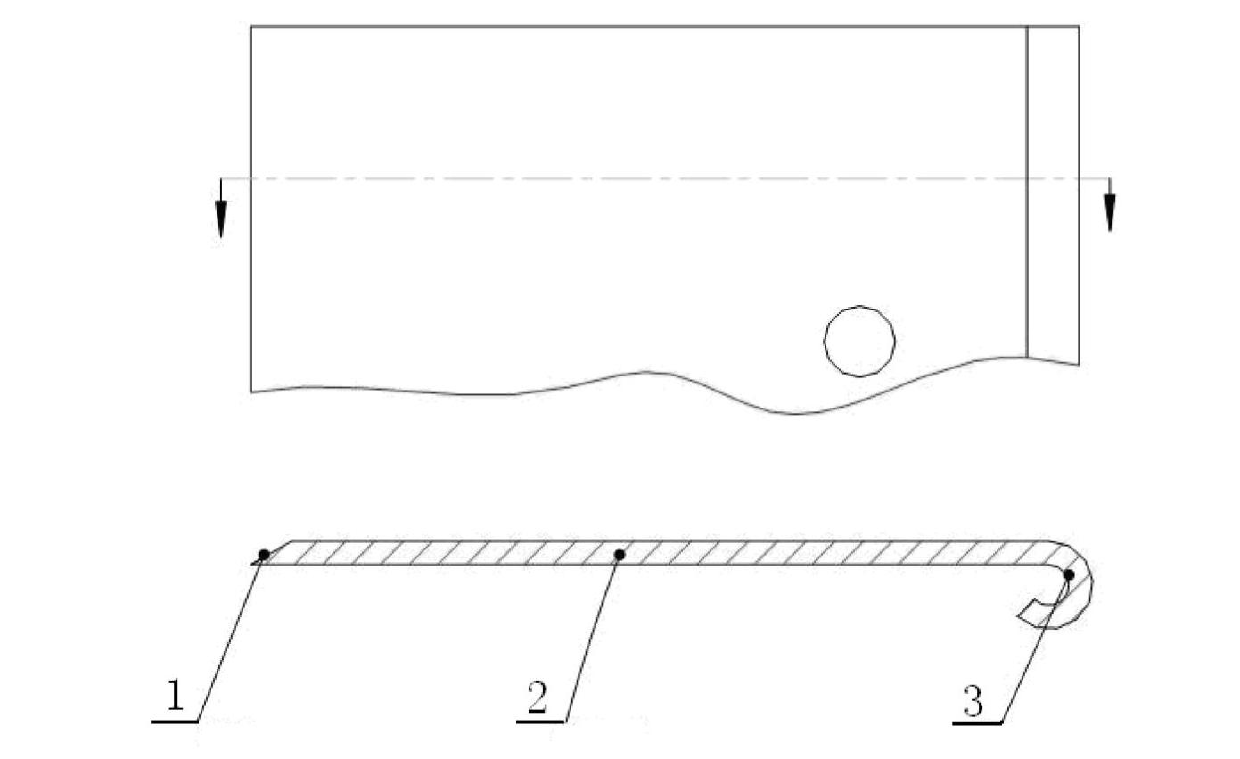
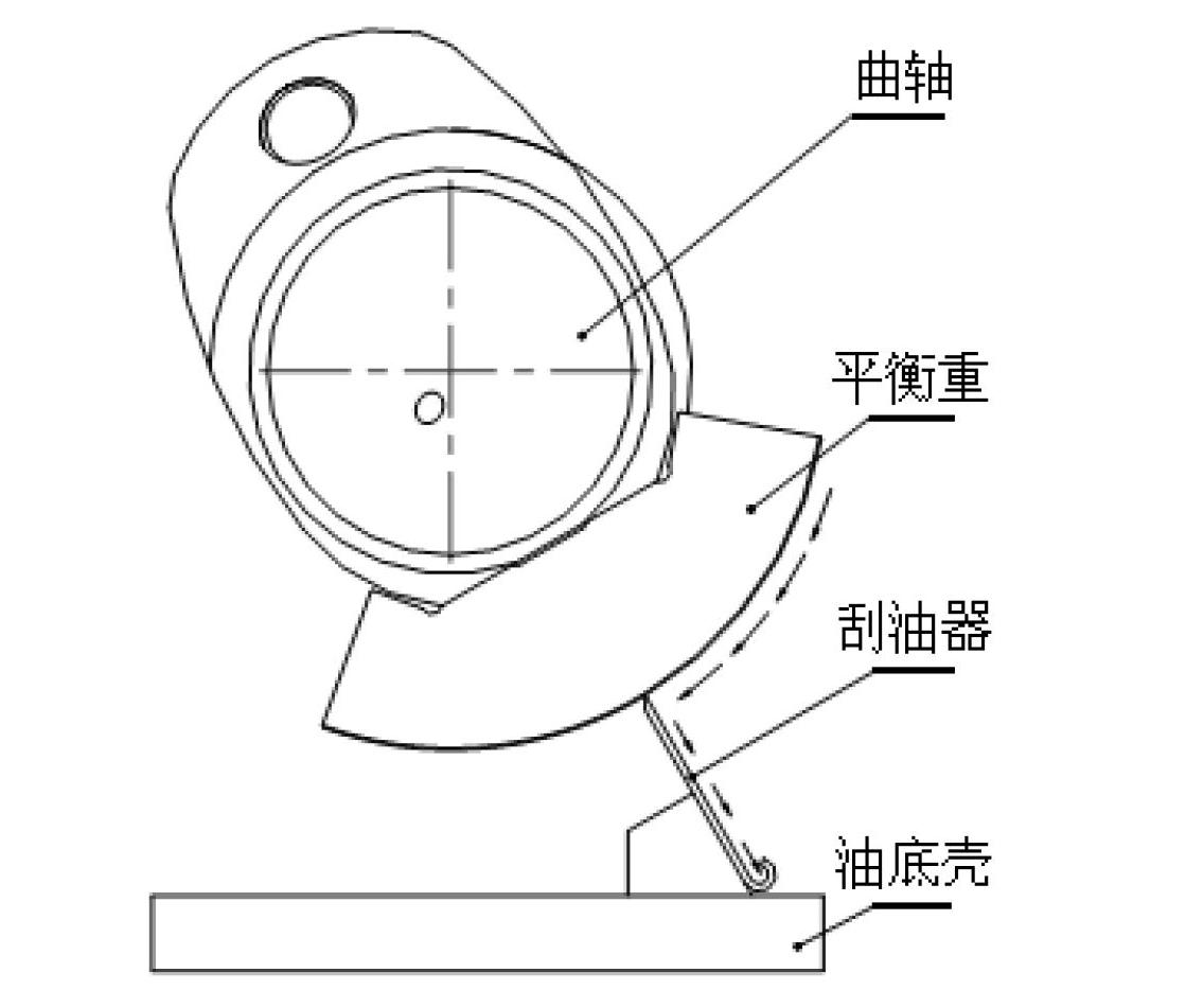
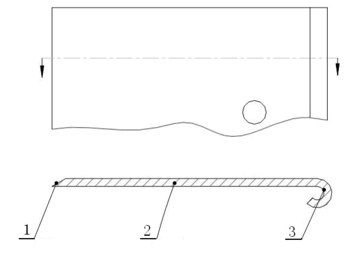
[0011] A crankshaft oil scraper for an internal combustion engine, including three parts: an oil scraper 1, a baffle plate 2, and a diversion groove 3. The oil scraper is a plate-shaped structure made of stainless steel, and the oil scraper is obliquely fixed on the oil pan On the top, it forms a fixed angle with the tangent direction of the crankshaft rotation and there is a gap with the crankshaft; there is an oil scraper 1 on the baffle 2, and the tip of the oil scraper 1 is in contact with the outer circumference of the balance weight, and the baffle 2 is located along the On the splashing path of oil droplets in centrifugal motion in the crankshaft rotation tangential direction, the end of the baffle plate 2 is provided with a diversion groove 3, and the front and rear oil pools of the oil pan are formed under the two ends of the diversion groove 3.

[0012] work process:

[0013] When the balance weight rotates through the oil scraper, the oil film attached to the balanc...


PUM


Abstract

The invention discloses a crankshaft oil wiper of an internal combustion engine. The crankshaft oil wiper of the internal combustion engine comprises an oil scraper (1), a flow baffle plate (2) and a diversion trench (3). The oil wiper has a plate-like structure made of stainless steel, is obliquely fixed on an oil bottom shell, and forms a fixed included angle with the tangential direction of rotation of a crankshaft, and a gap is formed between the oil wiper and the crankshaft; the oil scraper (1) is arranged on the flow baffle plate (2); the tip of the oil scraper (1) is in contact with the outer circumference of a balance weight; the flow baffle plate (2) is positioned in a splashing path of an oil drop which makes eccentric movement along the tangential direction of the rotation of the crankshaft; the diversion trench (3) is arranged at the tail end of the flow baffle plate (2); and front and back oil tanks of the oil bottom shell are arranged below two ends of the diversion trench (3). The crankshaft oil wiper of the internal combustion engine is novel in structure and simple in process, so that lubricating oil flows back quickly, the atomization of high-speed oil drops in a crankshaft case can be prevented, the waste gas pressure in the crankshaft case is effectively reduced, and the pollution caused by the internal combustion engine to the environment is reduced at the same time.

Description

[0001] technical field [0002] The invention belongs to a component of an internal combustion engine, in particular to a crankshaft oil wiper for an internal combustion engine. Background technique [0003] With the improvement of the internal combustion engine's strengthening index, the exhaust gas pressure in the crankcase has become an increasingly prominent problem. One of the important reasons is that the current internal combustion engine has not prevented the high-speed oil drop atomization due to the high-speed rotation of the crankshaft. related technologies. Contents of the invention [0004] The invention aims to solve the problem that the oil droplets are atomized when the crankshaft of the internal combustion engine rotates at a high speed, resulting in a high exhaust gas pressure in the crankcase. [0005] Technical scheme of the present invention: [0006] A crankshaft oil scraper for an internal combustion engine, including three parts: an oil scraper 1,...

Claims


Application Information

Patent Timeline
Patent Type & Authority Applications(China)
IPC IPC(8): F01M11/00
Inventor 辛花强智臻姚亮宇郭昌明闫玮熊必伟陈闯
Owner NO 70 INST OF CHINA NORTH IND GRP
Why Eureka
Try Eureka