Manufacturing method of ultrathin heat-conducting patch and ultrathin heat-conducting patch

A production method and technology of heat conduction stickers, which are applied in indirect heat exchangers, lighting and heating equipment, cooling/ventilation/heating transformation, etc., can solve the problem of poor heat exchange capacity on the surface of ultra-thin heat conduction stickers and difficulties in effectively solving heat dissipation devices Heat dissipation problems, limited internal space of electronic products and other problems, to achieve the effect of shortening the heat dissipation time, improving the heat dissipation effect, and uniform and meticulous distribution

Pending Publication Date: 2020-12-08
唐山达创传导科技有限公司
View PDF0 Cites 2 Cited by
  • Summary
  • Abstract
  • Description
  • Claims
  • Application Information

AI Technical Summary

Problems solved by technology

[0003] Due to the limited internal space of electronic products and the substantial increase in heat flux, traditional heat dissipation devices have been difficult to effectively solve their heat dissipation problems
With the development of demand, some advanced heat dissipation technologies have appeared on the market, one of which has a strong competitiveness in heat conduction and heat dissipation solutions, such as ultra-thin heat conduction patch, the existing ultra-thin heat conduction patch has two upper and lower cover plates In the process of truncation and sealing welding, it is easy to be damaged or broken, which will increase the probability of fluid leakage in the cavity. The heat dissipation performance of the existing ultra-thin thermal pads is often weak. The traditional structural design Does not have a capillary structure Small pores and high density affect the diffusion of liquid working fluid, resulting in uneven distribution of the working fluid, and the small capillary force affects the circulation speed of the working fluid, making the surface heat transfer capacity of the ultra-thin thermal pad poor. , thereby affecting the service life of electronic equipment

Method used


Image

  • Manufacturing method of ultrathin heat-conducting patch and ultrathin heat-conducting patch
  • Manufacturing method of ultrathin heat-conducting patch and ultrathin heat-conducting patch
  • Manufacturing method of ultrathin heat-conducting patch and ultrathin heat-conducting patch

Examples


Embodiment 1

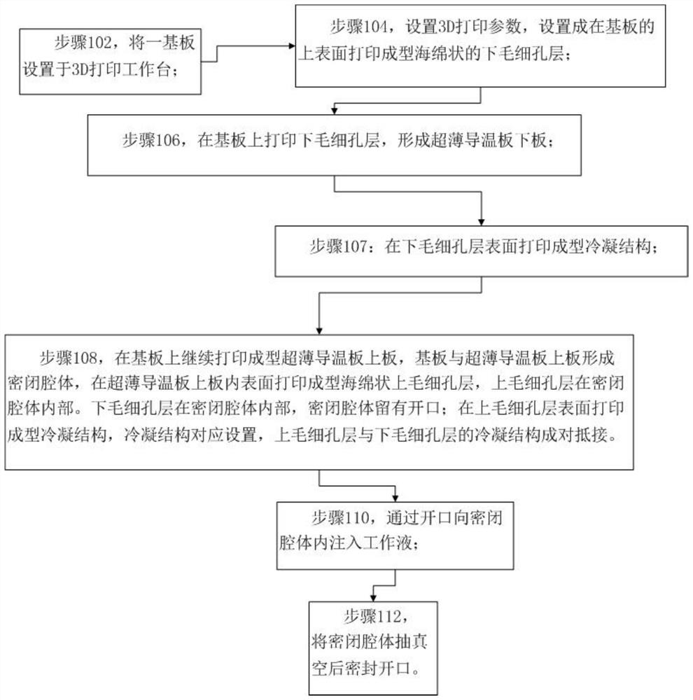
[0043] refer to figure 1 As shown, a manufacturing process of an ultra-thin heat conduction patch includes the following steps:

[0044] Step 102, setting a substrate on the 3D printing workbench;

[0045] Step 104, setting 3D printing parameters, and setting it to print and form a spongy lower capillary layer on the upper surface of the substrate;

[0046] Step 106, printing the lower capillary layer on the substrate to form the lower plate of the ultra-thin heat conduction patch;

[0047] Step 108, disposing an ultra-thin heat-conducting patch upper plate on the upper surface of the substrate, the substrate and the ultra-thin heat-conducting patch upper plate form a closed cavity, the lower capillary layer is inside the closed cavity, and the closed cavity has an opening;

[0048] Step 110, inject working fluid into the sealed cavity through the opening;

[0049] Step 112, vacuumize the closed cavity and then seal the opening.

[0050] With this implementation method, th...

Embodiment 2

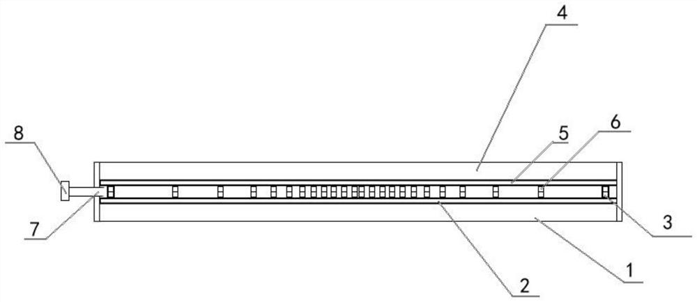
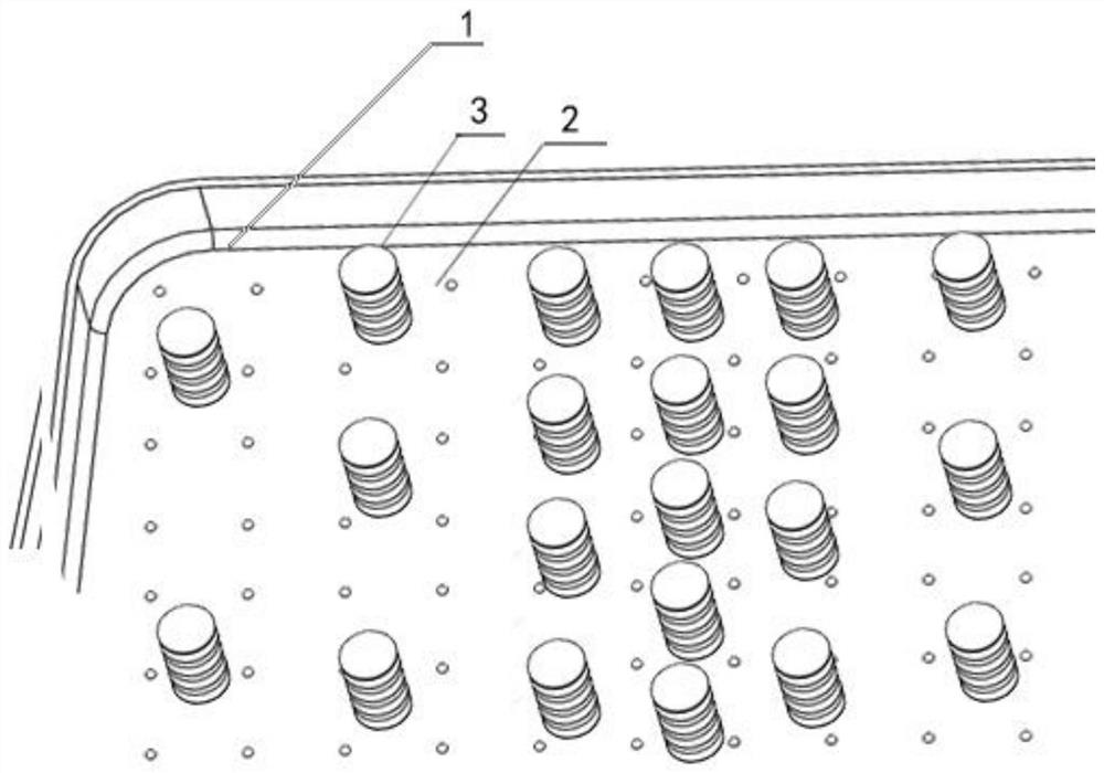
[0068] refer to figure 2 , an ultra-thin heat conduction patch, including a substrate 1, a lower capillary layer 2, a condensation structure 3, an upper plate 4 of the ultrathin heat conduction patch, an upper capillary layer 5, a condensation structure 6, an opening 7, and a sealing valve 8. Print the lower capillary layer 2 on the substrate 1 to form the lower plate of the ultra-thin thermal conductive patch; continue to print and form the upper plate 4 of the ultra-thin thermal conductive patch on the substrate 1, and the substrate 1 and the upper plate 4 of the ultra-thin thermal conductive patch form a closed cavity body, on the inner surface of the ultra-thin heat-conducting patch upper plate 4, print and form a spongy upper capillary layer 5, and the upper capillary layer 5 is inside the closed cavity. The lower capillary layer 2 is inside the closed cavity, and the closed cavity has an opening 7; the condensation structure 6 is printed and formed on the surface of the...


PUM


Abstract

The invention discloses a manufacturing method of an ultrathin heat-conducting patch and the ultrathin heat-conducting patch. The structure manufacturing of the ultrathin heat-conducting patch is achieved through a 3D printing technology. The ultrathin heat-conducting patch specifically comprises a base plate, an upper plate, capillary pore layers, condensation structures and the like. The ultrathin heat-conducting patch is manufactured before vacuumizing and liquid injection processes, is integrally formed in a 3D printing mode, and is firm and durable; meanwhile, ultrathin size manufacturingcan be achieved through the 3D printing technology; the condensation structures of the base plate and the upper plate are correspondingly arranged and pressed against each other in pairs, so that deformation of the heat-conducting patch is avoided; the state change speed of working liquid making contact with the capillary pore layers can be increased through manufacturing of the capillary pore layers of the base plate and the upper plate; and the thermal resistance of the ultrathin heat-conducting patch is lowered, and the heat dissipation efficiency is improved, so that the service life of electronic equipment is guaranteed.

Description

technical field [0001] The invention relates to the technical field of heat dissipation, in particular to a method for manufacturing an ultra-thin heat-conducting patch and the ultra-thin heat-conducting patch. Background technique [0002] With the rapid development of electronic integration technology, electronic equipment is developing in the direction of miniaturization and thinning, and the integration level of the system is getting higher and higher. On the other hand, the application of high-power components in electronic equipment increases the thermal power consumption sharply, and the resulting heat does not have enough space to dissipate, which directly affects the working performance and service life of the product. Statistics show that it is about 40%. This is due to the fact that the thickness of electronic equipment is getting thinner and thinner, and the power consumption and heat generation are also increasing. The traditional heat sink has a larger structur...

Claims


Application Information

Patent Timeline
Patent Type & Authority Applications(China)
IPC IPC(8): F28D15/04H05K7/20B22F3/105
CPCF28D15/046H05K7/20336
Inventor 任思宇王岩
Owner 唐山达创传导科技有限公司
Why Eureka
Try Eureka